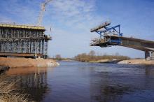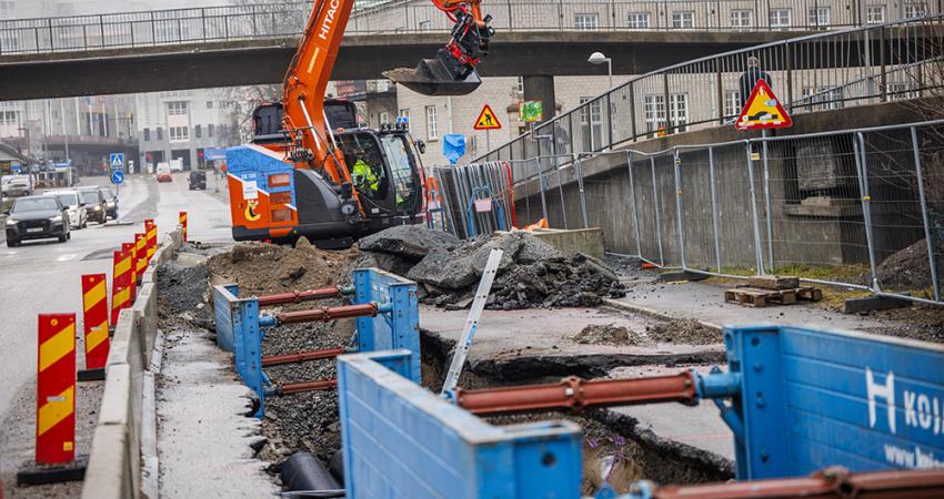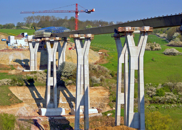
Innovative formwork systems have been used to construct a variety of bridge structures. Patrick Smith reports
As part of the work on Germany's new A4 autobahn near Eisenach, the contracting joint venture awarded the formwork contract for two of the three viaducts toThe contract also includes on site pre-assembly of the forming carriage on both sites, first-time assembly, repositioning onto the second superstructure of each bridge, and final dismantling, al to an extremely tight construction schedule.
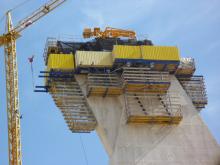
To meet the construction deadlines for both bridges, the Doka Competence Centre CC4 designed the composite forming carriage for the Böbertal Viaduct in such a way that it also took account of the 414m long Nessetal Viaduct.
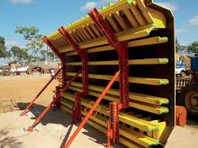
"The Doka technicians reached deep into the modular 'construction kits' of the SL-1 heavy-duty supporting system and the Top 50 large-area formwork to make it possible to adjust the width of the transverse framework using 3.3m long adapter pieces, with no need for complicated custom steel components," says Doka.
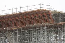
"Also, the fact that the formwork gangs are suspended using the Tie-rod system 20.0 makes formwork set-up and removal much easier, as it reduces the number of anchoring points, saving time, labour and equipment costs." To transfer the huge forces from the cantilever slabs via the formwork elements into the heavy structural steelwork of the forming carriage and thence into the bridge structure itself, the Doka formwork experts designed an undergirding support for the cantilever-arm elements.
The Tie-rod system 20.0 is also being used to suspend the 7.66m wide inside formwork of the Nessetal Viaduct. The inside formwork elements, together with the platform, are advanced underneath the finished deck slab, on roller supports and roller girders that are integrated into the inside formwork elements.
"This roller-drawer principle has proven to be a fast and convenient solution on numerous projects in the past," says Doka.
The inside haunches were formed with the aid of multi-purpose walings WU16 and custom adjustment plates, in order to close the loosely formed infill zones between the inside formwork elements and the upper flanges of the trough. The custom adjustment plates are needed because of the diagonal struts in the trough, as they can easily be unbolted to allow the inside formwork to advance, and then bolted in place in the next casting section, with only a minimum of labour. This prevents any collisions between the inside formwork and the structural steelwork.
The steep embankments and limited suitable storage and assembly space have made site erection work much more difficult on both bridges. This is why (following a specially-tailored assembly plan) all the component assemblies were hoisted up onto the steel superstructure at the earliest possible time, for final erection in situ.
To do this, three travelling units were first placed onto the superstructure and towed forward by around 15m to enable the remaining three travelling units to be connected behind them. After this, the platform units and the cantilever arm elements (consisting of Top 50 beam grilles) were suspended from the travelling units. After this, the construction was faced with tongue-and-groove board formwork at right-angles to the carriageway deck.
A site erection team of experienced Doka staff erected the overslung composite forming carriage on schedule on the first superstructure of the Böbertal Viaduct, and later repositioned it onto the second superstructure.
Following completion of the Böbertal Viaduct, the same team performed the dismantling work, as well as the subsequent site erection, repositioning and dismantling operations on the Nessetal Viaduct, in perfect liaison with site management on each occasion.
EUROVIA Group site manager Jörg-Thomas Schulz and foreman René Herzbruch, said: "With this system we've really managed two at one go. Our people have been getting on with the equipment just fine, and we've been saving time and money."
Sitra Bridges
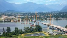
As one of the most important traffic links in the country's road network, linking Sitra and the capital Manama, the previous Sitra Bridges had reached the end of their service life and could no longer cope with increased traffic volumes.
The dual two-lane roads and at-grade junctions needed replacing by a dual three-lane highway and a three-level grade-separated intersection at Umm Al-Hassam, a first for Bahrain. This new configuration is designed to provide excess capacity for the heavy rush-hour traffic loads, which exceed 6,000 vehicles/hour.
To maintain traffic flow and services, the new bridges and utility conduits were built alongside the existing ones and switched out on completion. For main contractor Berhad Gamuda, the key to achieving these goals was to ensure the formwork and shoring was up to the challenge.
Following a competitive tender process, RMD Kwikform was awarded the formwork and shoring contract to assist in the construction bridges and flyover sections.
Key to successful creation of the new dual three-lane highway was marrying the needs of the tight programme and budget with the requirement for minimum disruption to the existing road network.
For RMD Kwikform's engineering team, headed by Shekhar Sawant, to achieve these goals practical yet safe design solutions were required.
The trust and interaction with Berhad
"What Berhad Gamuda was looking for was an equipment supplier that could support it technically and logistically to supply formwork and shoring solutions to key parts of the project.
"With east to south and north to south flyovers making up a large proportion of the new highway, and underpasses used in other areas, the range of equipment required was significant. Special parts and complex detailing also required specific engineering attention. With over 1,050tonnes of equipment used over a three-year period, the scale of project management and delivery required a huge amount of planning and onsite support, in the form of RMD Kwikform site assistance technicians." For RMD Kwikform there were various phases to the project. One was the 12m high, 1.2m thick Umm Al-Hassam underpass walls, which were created using a single-sided climbing formwork system. This was then followed by the use of Rapidshor shoring in a modular format as back-propping to transfer the additional loads applied on to the underpass slab from the flyover deck supports.
But it was the flyovers themselves that required the most equipment and engineering support, requiring the use of complex side forms in order to achieve the design requirements. With Rapishor shoring supporting Superslim Primary and GTX Secondary beams used for the complex bridge deck, complete with wedge-shaped side forms, the varying widths of the flyover decks were achieved.
The 390m long east-south flyover had six spans from abutment to abutment while the east-north flyover measuring 185m, with five spans from abutment to abutment.
In addition to the flyover and underpass systems used, RMD Kwikform also supplied over 280tonnes of side form formwork consisting of a combination of Kwikstage, Rapidshor Support with Soldier and special-shaped steel walers to support GTX Beams and plywood to form complex profiles for the construction of the Marine bridges.
Relief road
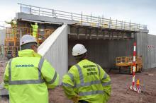
Equipment from Harsco Infrastructure has helped specialist contractor JOS Structures build two concrete bridges as part of the £63 million (US$102 million) Selly Oak Relief Road project near the city of Birmingham, UK. One will carry the Birmingham and Worcester Canal while the second, adjacent to the canal bridge, will carry the Birmingham and Gloucester Railway line over the new relief road.JOS Structures used Harsco's LOGIK 60 modular wall panel formwork system to cast the mass concrete piers at either end of the two 70m long bridges. Individual panels are clamped rigidly together with Harsco's ALL (aligning/levelling/locking) clamps which make the system very quick to assemble.
As the bridges feature decorative architectural details, such as arched and fluted parapets, which must be finished to a very high standard, all the formwork panels (with the exception of the LOGIK 60 system) were fabricated by JOS Structures' carpenters entirely by hand.
The main decks of both bridges were formed using Harsco's CUPLOK and GASS systems, which like LOGIK 60 are quick and economical to use due to their modular design. The parapet and wing-walls were formed using DU-AL aluminium beams with MkII Soldiers used for vertical support.
The canal bridge has been built in its final location with the canal itself temporarily diverted around it, and the railway bridge was picked up and slid into position during a 101-hour possession.
The 70m long, 3,846tonne concrete structure is one of the biggest concrete structures ever installed in this way, says John Daft, project manager for main contractor
Birse Civils has been excavating 40,000tonnes of material from the 15m high, 100m wide embankment built in 1796 to carry the canal, so the new road can go underneath.
FUVI introduces new system
An innovative Honey MDC slab/beam system has been introduced by Vietnamese formwork specialist FUVI and it is said to offer greatly reduced striking programmes and increased re-use cycles.
The Drophead design allows the slab/beam forms to be removed in 3-4 days for transfer to the next level or location, while continuing to support the newly-formed slab or beam throughout the full 14-21 days curing sequence.
The new Drophead has been designed for use with Fuvi's Honey MDC slab/beam system, with a main panel size 500 x 1,000mm and 90mm thickness or smaller size panels and combinations.
The Drophead comprises a core bar, a small plastic panel head, which supports the concrete labour beam at all times, and an outer shoulder which supports the adjoining Honey slab/beam panels.
Both the Drophead and outer shoulder are fabricated in special plastic and the core bar is made of high strength steel.
When the panel forms are removed, by releasing the outer shoulder down the supporting core bar, the Drophead remains in place to support the full weight of the concrete slab.
Canadian project for PERI
The Autoroute 50 extension project involves a 90km long two-lane road connecting Gatineau and Montreal in Canada.
As part of this project a 14.32m wide, 380m long bridge crossing the River Rouge is under construction by Construction Demathieu & Bard (CDB) from Saint-Jérôme, Quebec.
PERI supplied the formwork for construction of the two abutments of the bridge and four piers which are between 21m to 66m high.
The project had rigorous requirements for concrete formwork of the piers. The formwork system must be light enough to match the site crane capacity. At the same time the formwork must be strong enough to withstand high concrete pressures resulting from concrete in a 6m high pour.
Because of very dense reinforcement in the piers, the tie location in the formwork should be flexible enough to allow for optimised layout of the ties.
VARIO GT 24 girder wall formwork combined with CB 240 climbing brackets provided the ideal solution for the pier formwork. The climbing system supplied comprised six platform levels. The top three levels were for reinforcement and concreting work, the fourth level was the main level for formwork and the two levels of trailing platforms were dedicated for removal of climbing cones and concrete patching work.

