Specially designed and constructed formwork is being used to create some iconic bridges worldwide The Golden Ears Bridge over the Fraser River will unite the municipalities of Richmond, New Westminister and Delta in the scenic British Columbia province of Canada. The bridge, part of a CAD$800 million (US$670 million) project, is an 'extra dosed' cable stayed bridge, which means the deck will be supported by both cables and the structure itself. This design reduces the overall height of the two towers as req
Specially designed and constructed formwork is being used to create some iconic bridges worldwide
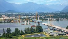
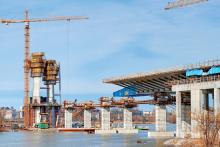
The Golden Ears Bridge over the Fraser River will unite the municipalities of Richmond, New Westminister and Delta in the scenic British Columbia province of Canada. The bridge, part of a CAD$800 million (US$670 million) project, is an 'extra dosed' cable stayed bridge, which means the deck will be supported by both cables and the structure itself. This design reduces the overall height of the two towers as required for a simple cable stay bridge.Started in the summer of 2006, the six-lane, 4.3km tolled bridge project entails the construction of numerous smaller bridges, ramps, viaducts and the main river bridge, which are all scheduled to be completed by the summer of 2009.
The entire Golden Ears Bridge project is some 14km long and also includes new arterial roads connecting the bridge to the existing road network on both sides of the river, and municipal road upgrades to improve traffic flow.
The Golden Crossing General Partnership, owned by Bilfinger Berger Project Investments, has a 35.5 year contract with
TransLink, the South Coast British Columbia Transportation Authority, plans, finances implements and operates an integrated transportation system, with responsibility for major regional roads as well as public transit.
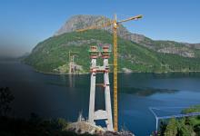
The Golden Ears Bridge consists of four towers with two pylons each towering 86m and spanning over 242m apart. The total length of the bridge once completed will span 970m over the Fraser River.
Systems supplied for the project by
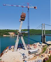
"The Golden Ears Bridge project dictated that a safe and productive forming system would be required to meet the aggressive schedule. The Automatic Climbing System (ACS) was used for this project because of its flexibility required for the differing geometric shapes of the pylons and for its ability to function in high winds," says PERI.
The 10tonne hydraulic piston used in the ACS system provides the worker with the ability to climb the entire system at a rate of 0.5m/minute in a safe and secure fashion.
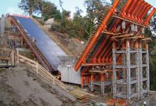
Other systems supplied by PERI for the job included the TRIO Wall formwork system and the PERI Bridge Brackets. The TRIO system is a modular steel frame system used to form the abutment walls, while the PERI Bridge Bracket system was used in forming the edge of the approach ramps. The brackets gave the workers an area of over 2.5m of working space from the edge of the existing structure.
It is said that the new bridge will improve the economic competitiveness of Metro Vancouver by improving travel times, reducing regional congestion, and opening up access to employment, markets, services, facilities and recreational opportunities.
Construction of the bridge and road network is creating more than CAD$1 billion in economic activity and 7,000 person-years of employment.
World beater Visitors to the water and sustainable development-themed, International Expo Zaragoza, 2008 in Spain, which ended in September, made the journey to the fantastic site housing 5,000 shows, 2,000 experts and 140 pavilions which was made more exciting, thanks to the completion of the Third Millennium Bridge.
Spanning the Ebro River in the Aragon region in the north-east of Spain, the E34 million (US$43.7 million) bridge is the world's largest suspended concrete arch bridge.
Built by Spanish construction specialist,
Designed to carry six traffic lanes, two bicycle lanes and two pedestrian lanes across a deck width of 43m, the impressive concrete arch of the bridge reaches up to 36m from the deck and weighs some 5,000tonnes. Connected to the 24,000tonne composite precast and cast in situ deck, each of the 64 cables supporting the deck from the arch is charged with withstanding tensions of up to 300tonnes.
With ground works and site preparation beginning in September 2005, the first of 1,700tonnes of RMD Kwikform Ibérica equipment required to create the structure was taken onto site in August 2007. Work started on the nine-month formwork and falsework programme that would see RMD Kwikform Ibérica hand over the completed bridge two weeks before schedule.
The important and iconic structure, the gateway to the Expo Zaragoza 2008, had to be completed within the defined programme time. With a team of engineers dedicated to the design process, work on the formwork and falsework for the main design of the bridge took over ten weeks of engineering time to complete.
The load tolerances demanded by the client and location of the bridge proved to be the most important considerations in the overall design.
Alberto Aldama, an RMD Kwikform engineer who worked on the project, explained: "The design of the main structure had to have the minimum batter or displacement because of the very low load tolerances permitted by the client. This meant we had to look at the equipment we had available and design special components in order to meet the tolerances required.
"We also had to consider how these tolerances would be affected by the considerable wind force that would be placed on the bridge. This wind force was a direct result of where the bridge is located. In fact because the El Bierzo valley is in close proximity to the project, we had to contend with what can only be considered as a naturally made wind tunnel that is capable of generating enormous forces and pressures directly onto the bridge structure itself." With the RMD Kwikform Ibérica engineering team focused on developing a low tolerance high strength system, the design process was further challenged by the need to put the cables into place before concreting of the keystone of the arch was completed and the falsework removed. In order to achieve this additional requirement, the falsework system design had to be altered to accommodate the partial removal of equipment in set areas, without affecting the structural integrity of the bridge and falsework system.
This partial removal meant that access to the cables within a reduced space was possible with the design allowing access for the machinery required to make sure the cables could to be worked through, without affecting the main structure. Once this process, which involved cable placement every 6m, was completed the equipment was then able to be dismantled.
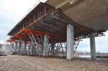
With all of the issues and challenges taken into consideration at the design process, the main formwork and falsework structure itself was based around exploiting the strength of RMD Kwikform Ibérica's Megashor, heavy duty 1000 kN shoring system.
With a supporting base built further out from the left bank of the Ebro River used to help support the construction of the main deck, the deck and support piers were built for the whole of the bridge prior to the arrival of RMD Kwikform Ibérica equipment.
The design called for two main supporting legs curving up to meet in an upturned V-shaped support for the main arch, at each end of the bridge, and the first shoring and formwork challenge was to concrete these parts of the structure.
Using a combination of Megashor, steel beams and Kwikstage shoring, the formwork and falsework support for the four legs was erected, with the legs poured in four main curved sections climbing up towards the arch. At the same time Megashor towers were erected on the main deck as well as the standard steel beams for the gantries at each end.
Alberto said: "Once we reached erection stage the project was all about achieving maximum productivity. This is why we simultaneously erected the leg support and commenced pouring, while also erecting the Megashor towers for the main arch. In total there were 12 separate Megashor tower arrangements constructed at a total of six different heights.
Due to the positioning of the deck support piers, each tower was placed at 6m intervals in order for the formwork structure to have enough support to be fixed into position.
"This was due to the fragility of the hollow composite precast and cast in situ deck, which meant that the arch had to be cast in situ in 12m sections." With tolerances and stresses varying across the arch structure, special reinforced steel beams, anchor parts and wooded supports were manufactured to support the main formwork and falsework system.
"Very special formwork" Already a familiar approach in the building of prestressed concrete bridges, the semi-integral bridge concept can also be applied to composite bridges, where it further reduces the maintenance intensity of the bridge construction.
One of the first composite bridges in Germany to be based on the semi-integral concept was built by the construction firm of VSTR GmbH Rodewisch.
For the project in Erla, in the German State of Saxony, VSTR relied on the concept and products provided by the Doka formwork experts.
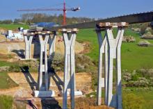
The Am Schwarzwasser Bridge is 160m long and on average around 10m wide and is a classic composite bridge construction with a cast-in-place (CIP) deck slab cast on longitudinal steel girders.
"Passing across two roads, a river and a railway line, with broadening zones on both abutments, varying centre-to-centre spacing of the structural steelwork on one abutment, and pier-heads which had to be cast in one single pour together with the respective section of the carriageway deck, this bridge was definitely not an everyday assignment," says Doka.
"Pouring the pier-heads together with the carriageway deck called for a very special formwork engineering solution and a great deal of professional know-how. Working closely with Doka's nearby Dresden branch, the Doka specialists greatly facilitated the project workflow with their planning input." The company says that the assignment was solved by using an overslung composite forming carriage and by dividing up the bridge into a 'typical zone' between the piers, a 'pier zone' and a 'stationary formwork solution' in the zone with varying centre-to-centre spacing.
Work on the forming carriage (20m long and consisting of four segments) on the structural steelwork, ready for handover to VSTR, was completed in six workdays, and then handrail planks and form-ply in the adjustment zones between the carriage and the structural steelwork were added.
After the welding operations on the bridge had been finished, the carriage was towed to its first pouring position.
"In terms of how to operate the forming carriage, it is more or less self-explanatory. All the remaining forming operations, like making fine adjustments to the forming carriage and fitting the stop-end formwork and side formwork, did not need any further help from us," says Doka.
To take account of the maximum permitted load-bearing capacity of the steel longitudinal girders in the typical zone, the weekly pours were sequenced in an irregular 'back-step' pattern.
In the pier zones, to facilitate fitting the formwork for the four pier-heads that each had to be cast in a single pour, the forming carriage was designed so that it could quickly be separated into two 10m long parts. These two parts were then positioned on either side of the future pier-head and joined together again with short longitudinal girders.
"The concrete finish achieved here impressed both VSTR and its public-sector client," says Doka.

