1. Introduction
It was proposed to carry out a fully evaluated and monitored paving trial on a portion of the M7/P82 near Pinetown, approximately 20km inland of the coastal city of Durban. The trial section is located on the slow lane of the westbound carriageway of the M7/P82 between the Hans Dettman Highway overpass and the Thistle Road underpass and spans 172m.
The M7 is a strategic route in eThekwini Metropolitan Municipality that primarily links Durban Harbour with the N3 Durban-Johannesburg National Route. As such, it carries extremely heavy traffic with 20-year cumulative axle loading in the order of 100 MESA - million equivalent standard axles. In general, this route has a posted travelling speed of 100kph though the position of the trial is on a grade with heavy vehicle speeds averaging around 60kph. This further exacerbates the extreme loading environment
Given the location, current condition and traffic volumes, this section of the M7 was considered ideal to establish long-term performance of the rHDPEa under extreme traffic loading conditions. This paper reports on the condition of the section selected for the trial, the preparation of the site, the asphalt mixes used in the base and surfacing and comments on the short-term performance of the trial.
2. Traffic Loading
A seven-day classified traffic count was undertaken by specialist traffic monitoring company Mikros between November 3 and 9, 2021 on the slow lane close to the northern end of the trial section. A sensitivity analysis of the cumulative traffic loading over 10-, 15-, 20- and 25-year structural design periods, in which the proportion of laden heavy vehicles was varied, was calculated in accordance with the method prescribed in TRH4 pavement design catalogue. Given the sluggish economy indicated by the country’s low gross domestic product, GDP, it was decided to adopt a maximum traffic growth rate of 2%.
Salient details of the classified traffic counts are tabulated in Table 2.1 while Figure 2.1 indicates the traffic loading for the 10- to 25-year structural design period at a 2% growth rate.
| 5 | 7226 |
| ADTT | 2796 |
| Percentage heavy vehicles | 38.7 |
| Truck split (%): Short: Medium: Long | 20.15.65 |
| Average speed (heavy vehicles) | 61.2kph |

It is evident from the sensitivity analyses as can be seen in Figure 2.1 carried out on the M7/P82 that the traffic loading can be described as extremely heavy with cumulative loadings in order of 100 MESA likely to be achieved within a 25-year structural design period.

3. Pre-Trial Investigation and Assessment
A detailed visual inspection had been conducted on the M7 Trial section in accordance with TMH9 and TRH12 which indicated that the original pavement was in a poor condition, exhibiting severe rutting and isolated transverse cracking. Core specimens had been extracted from the existing pavement, these showed that an approximately 160mm thickness of asphalt consisted of three layers, an upper layer of continuously graded mix and lower layers of semi-gap graded mix. The photograph in Figure 3.1 shows the severe rutting in the left wheel path while the semi-gap graded asphalt in the lower layers is easily visible in the photograph of core specimens in Figure 3.2.

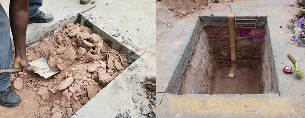
Pertinent details of a trial pit that was excavated within the trial section are summarised in Table 3.1. The photograph in Figure 3.3 shows the excavation of the strongly cemented layers in the trial pit while Figure 3.4 shows the fully excavated trial pit with change in colour of the cemented layers after the application of phenolphthalein visible; this is a clear indication that the layers were originally stabilised with either hydrated lime or cement. The quality of material found in the pavement layers have been classified in accordance with COTO, South Africa’s Committee of Transport Officials.
| Depth from Surface (mm) | Abbreviated Description | COTO Classification |
|---|---|---|
| 0 - 40 | Continuously graded asphalt | AC |
| 40 - 90 | Semi-gap graded asphalt |
AS |
| 90 - 150 | Semi-gap graded asphalt | AS |
| 150 - 300 | Weathered sandstone (strongly cemented) | G7 |
| 300 - 450 | Weathered dolerite (strongly cemented) | G6 |
| 450 - 780 | Weathered sandstone | G6 |
| 780 - 1000 | Weathered sandstone | G7 |
4. Preparation of the Trial Section
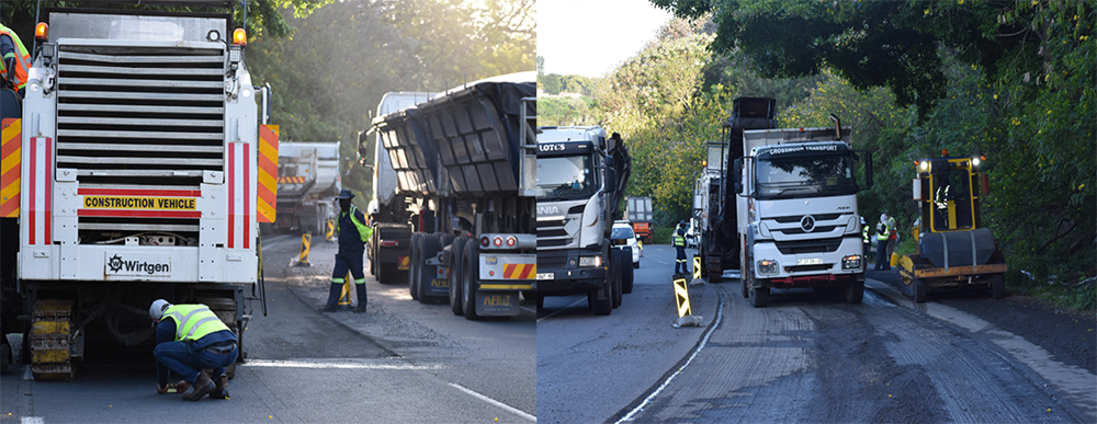
The section to be milled was measured and set out prior to commencing the milling operation. A milling machine with an effective cutting width of 2m was used. This meant that two adjacent cuts were required to remove the asphalt within the 4m width of the slow lane. The process of milling out the approximate 160mm thickness of existing asphalt is illustrated in Figure 4.1 and 4.2. The reclaimed asphalt (RA) was transported to Shisalanga Construction’s Cliffdale asphalt plant site to be prepared for use in other asphalt mixes.
5. Mix Properties
The binder used in the manufacture of the modified asphalt was prepared using the “wet method”; the pelletised recycled waste plastic (rHDPE) was digested in the hot bitumen. Reference should be made to the paper titled “Asphalt modified with recycled waste plastic in South Africa: Encouraging results of trial section performance”. It includes a full description of the binder preparation process. Salient details of the binder used in both EME and SMA* type mixes are presented in Table 5.1.
| Binder Grade | 70/100pen modified with rHDPE |
| Performance grading | PG58E-22 |
| Softening point (oC) | 59.2 |
| G*, δ at TIT, kPa and oC | 3.27, 58.0 |
| G*/sinδ,10rad/sec @Tmax, kPa | 7.041@ 58 oC |
| Dynamic viscosity Specification: < 0.90 |
0.28 |
| Storage stability @ 180 oC Specification: < 15.0 |
N/A |
| Flash point oC Specification: ≥ 230 | 270 |
| Binder Grade | 70/100pen modified with rHDPE |
| G*, δ at TTT, kPa and oC | 5.20, 50.6 |
| Mass change, % by mass fraction Specification: ≤ 1 |
N/A |
| JNR @ Tmax., kPa Specification: ≤ 1 | 0.058 |
| Aging ratio, G*RTFOT/G* Original Specification: ≤ 3 |
1.6 |
| G*δ at T, kPa and oC | 7.44, 44.93 |
| S(60s) at Tmin +10 oC, MPa Specification: ≤ 300 |
163 |
| M(60) at Tmin MPa/s Specification: ≥ 0.3 |
0.33 |
| Δ Tc=Tc,S-Tc,m, oC Specification: ≥ -5 |
-3.557 |
| Aging Ratio, G*PAV/G Original Specification: : ≤ 6 |
2.3 |
Pertinent details of the EME mixes used in the base layer are summarised in Table 5.2.
| TEST/ PROPERTY | EME 14 |
|---|---|
| Binder | rHDPE |
| Filler/ Binder ratio | 1.5 |
| Optimum binder content (%) | 5.2 |
| Richness modulus | 3.3 |
| Binder absorption (%) | 0.3 |
| Workability Voids at 45 gyrations | 2.8 |
| VMA (%) | 14.7 |
| VFB (%) | 79.0 |
| Modified Lottman | 0.923 |
| Stiffness modulus @ 20oC (10Hz) | 18621 |
| Fatigue 10Hz, 1,000,000με @ 10 oC | 298.56 |
| Hamburg Wheel Track (mm), 20,000 cycles at 50oC | 2.451 |
For Table 5.3, pertinent details of the SMA surfacing mix are summarised.
| TEST/ PROPERTY | SMA |
|---|---|
| Binder | rHDPE |
| Filler / Binder Ratio | 1.0 |
| Optimum binder content (%) | 6.3 |
| Film thickness (μmm) | 12.5 |
| Binder absorption (%) | 0.2 |
| Void in mix (%) | 4.7 |
| VMA (%) | 18.8 |
| VFB (%) | 73.5 |
| Modified Lottman | 0.952 |
| ITS (kPa) | 1 406 |
| Hamburg Wheel Track (mm), 20,000 cycles at 50 oC | 2.857 |
| Fatigue 10Hz, 200με @ 10 oC | 5,900,000 |
*Fatigue property reflected for SMA in Table 6.3 is for the pilot trial carried out on D755.
6. Construction of the Trial
The trial entailed replacing the 160mm thickness of the original asphalt with a 120mm thick EME-type base layer, constructed in two separate 60mm layers, followed by a 40mm Stone Mastic Asphalt (SMA) surfacing layer. Both the EME base and SMA surfacing mixes were paved using asphalt manufactured with bitumen modified with 6% rHDPE by mass of binder. The design of the new upper pavement layer works is presented in Table 6.1.
| Layer | Target Thickness | Material Description |
|---|---|---|
| Surfacing | 40mm | Stone Mastic Asphalt rHDPEa Asphalt Surfacing |
| Upper Base Layer | 60mm | EME type rHDPEa Asphalt Base |
| Lower Base Layer | 60mm | EME type rHDPEa Asphalt Base |
| Subbase | 300mm | Existing Cemented Layer |
Monitoring at the asphalt plant included the recording of asphalt temperatures of each of the three mixes used in the trial. The mix temperatures recorded at the asphalt plant and trial construction site for both the SMA surfacing layer and EME upper and lower base layers are presented in Table 6.2.
| Layer | Average Mix Temperature (°C) | Average Paving Temperature (°C) |
|---|---|---|
| SMA Surfacing | 154 | 146 |
| EME Upper Base | 168 | 159 |
| EME Lower Base | 174 | 153 |
Construction processes at the trial site, were extensively monitored. To mitigate cracking at the joints between the old and new asphalt, an approximate 5m transverse step joint was created at both ends of the trial. In the longitudinal direction steps of 200mm wide on the shoulder side and 100mm wide at the centre line side were provided.

Once the milling process was completed, the subbase was thoroughly cleaned using compressed air and brooms. The floor of the excavation was closely inspected to assess the condition of the existing remaining pavement layers while thickness measurements were undertaken every 10m to establish milling depth and to create a baseline for subsequent asphalt layer thickness measurements.
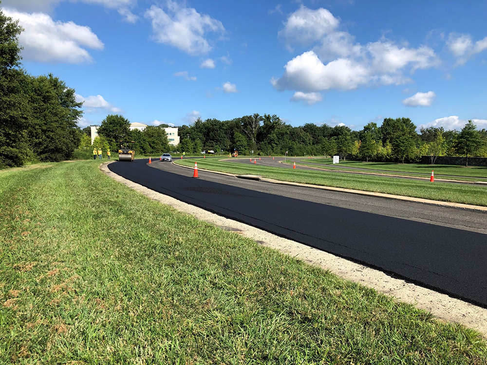
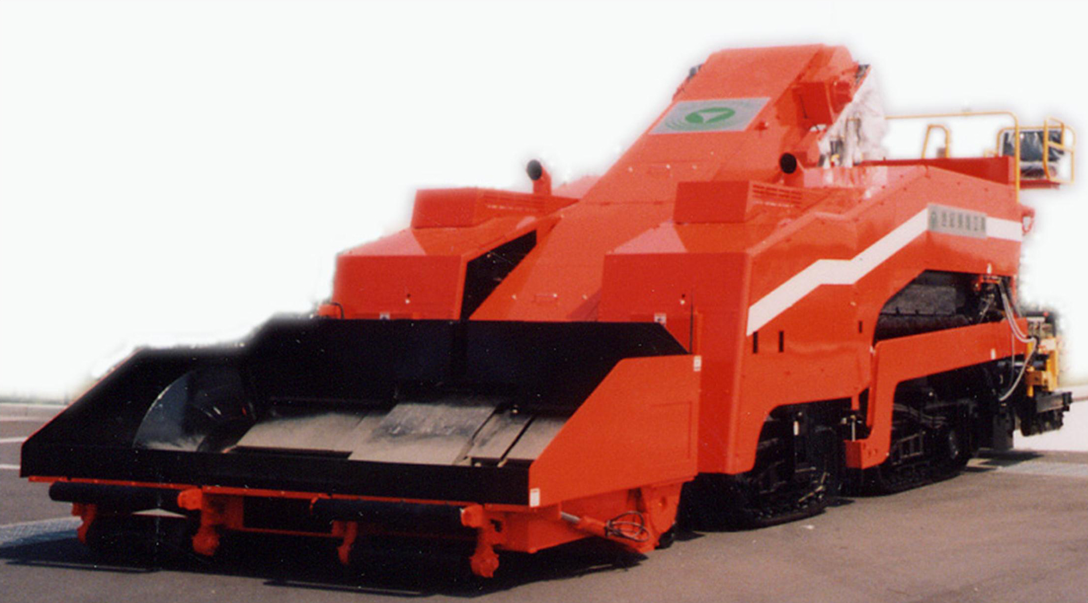
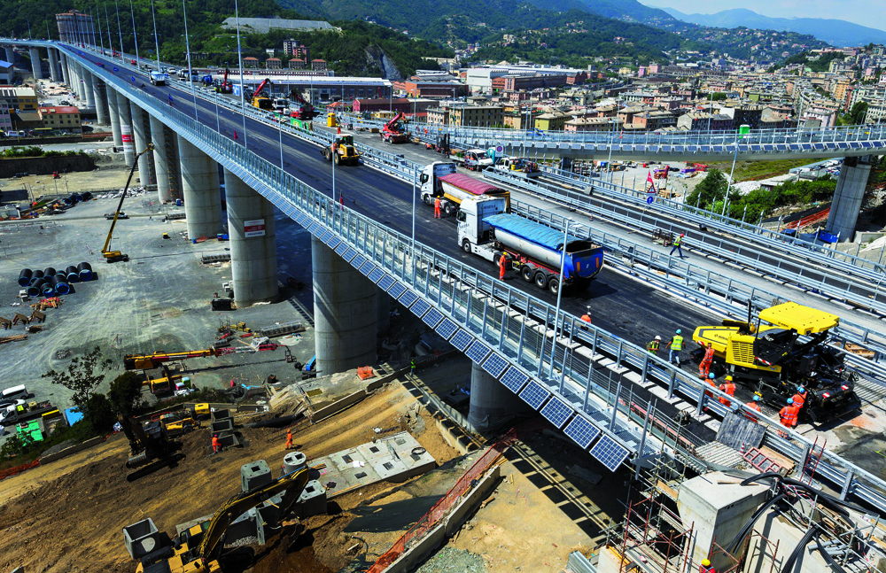
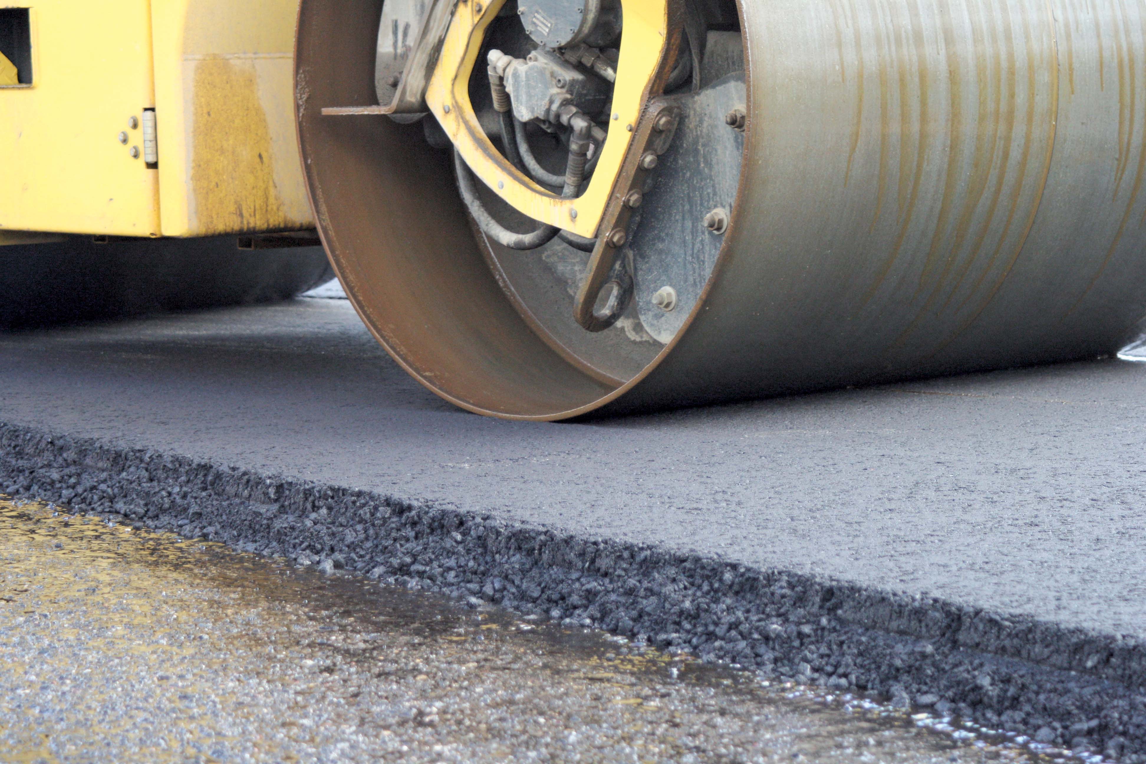
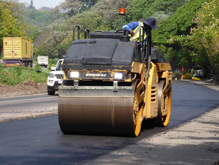
The paving process started once the first two trucks of asphalt mix had arrived on site, immediately followed by compaction using a Hamm 3-Point Static roller (13tonnes operating mass) and a Dynapac tandem vibratory roller (12tonnes operating mass). Paving of the upper EME type layer is shown in Figure 6.1 (image at the beginning of this article) while compaction using the static and vibratory rollers is illustrated in Figure 6.2 and 6.3.
Compaction testing following each pass of the rollers was carried out using a thin layer nuclear density gauge. This enabled the rate of compaction as well as the number of roller passes to achieve the required level of compaction to be ascertained. The rate at which the temperature of the asphalt layer decreased was also monitored.
Compaction was found to be easily attainable as the components include a warm mix additive. Typically, compaction could be achieved after four passes of the primary static roller and a further two passes of the tandem vibratory roller. Compaction results of the cores undertaken for both the EME and SMA layers are presented in Table 6.3.
| Layer | Avg. Relative Compaction |
|---|---|
| SMA Surfacing | 96.0 |
| EME Upper Base | 98.7 |
| EME Lower Base | 98.8 |
7. Post-Trial Assessment
 The post-trial assessment included detailed visual evaluation and instrumented testing utilising specialized equipment to measure structural and surface performance was undertaken by ARRB Systems once the asphalt layers had cooled sufficiently.
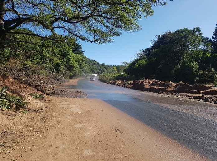
 Results to date show that the trial section is performing well, with no evidence of any structural or surface distress. This is remarkable, considering that the trial section was exposed to the severe flooding and landslides caused by heavy rainfall over two days in April this year - several weather stations recorded more than 300mm of rain over 24 hours - that affected eastern and south-eastern South Africa. Several weather stations recorded more than 300mm of rain over 24 hours. As shown in Figure 7.1 and 7.2, the M7 at the trial site was severely impacted, with piles of debris and water flowing over the surface for several weeks after the floods. Despite this, there has been no visual deterioration in the condition of the trial section.
8. Conclusions
The comprehensive monitoring of the processes, asphalt mix temperatures and laboratory testing at the plant and trial site together with the extensive supervision of the trial section provides useful information for further research into the properties and performance of asphalt manufactured utilising bitumen modified with rHDPE.
It is evident that the trial section constructed on the M7/P82 – which involved both the asphalt surfacing and base mixes manufactured using bitumen modified with 6% recycled rHDPE - is performing well under extreme traffic loading conditions.
Traffic loading calculations indicate that since the construction of the trial section over a six-month period the section has been subjected to approximately 3.0 MESA. There have been no visual signs of distress or deterioration. At the same time, it has been able to withstand the harsh impacts of the severe flooding caused by the heavy rainfall in the province of KwaZulu-Natal during this past April.
Full spectrum pavement testing on a three-month cycle, including deflection, friction measurement, riding quality, rut depth, automatic crack detection and traffic counts, will be carried out over a three-year period by ARRB Systems., following which, a comprehensive performance report will be compiled.

*EME-type and SMA-type asphalt mixes:
- EME is high-modulus asphalt based on the French technology called Enrobé à Module Élevé (EME) for pavements on highly trafficked routes, for example along urban bus routes and key motorways as well as roads subjected to high incidence of heavily laden trucks in industrial areas. It was developed in the 1980’s where low penetration - very hard, yet not brittle - bitumen binders are used to produce very stiff asphalt layers.
- SMA is stone mastic asphalt, sometimes called stone-matrix asphalt. It was developed in Germany in the 1960s and where the first SMA pavements were placed near the city of Kiel in 1968. It provides a deformation-resistant, durable surfacing material, suitable for heavily trafficked roads.
The author, Simon Tetley, is group executive for pavement and materials engineering at VNA Consulting, based at the Cape Town office in South Africa. He is also a director of the South African operation of ARRB Systems, a specialist service provider in road asset/pavement management solutions.


