Imaginative formwork, often using modular components, is helping to shape some challenging bridges worldwide. Patrick Smith reports
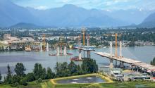
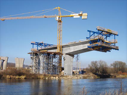
Traffic volumes in and around Prague have swollen massively in recent years, pushing the existing road network to the limits of its capacity. To permanently ease congestion in the Czech capital's centre, a multi-lane orbital motorway is under construction as a high capacity bypass for central Prague and to link up all the motorways and other major highways radiating from the city. One contract to the south of Prague includes a 236m long bridge across the River Vltava, and in terms of the formwork engineering involved, it is one of the most challenging sections of the new road.The two-part bridge deck is characterised by varying geometries, and is being built by
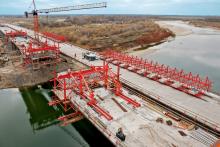
The Doka CFT was successfully premièred on the construction of the Elbe Bridge in north-eastern Czech Republic.
"A special feature of this construction project is the differing cross sectional geometries of the two statically separate decks. The left hand bridge deck is being constructed with a twin-cell hollow cross section (with a wider cantilever slab, to carry an extra traffic lane) and the right hand deck is designed as a single-cell box girder," says Doka.
With the CFT, both decks can be formed and cast with no need for time-consuming, costly modifications.
The advantages of the newly developed tie-rod girder are apparent where different deck cross sections have to be formed: they can be freely positioned in a tightly spaced grid anywhere along the entire length of the tie rod girder, enabling them to be perfectly tailored to the bending moment. The tie-rods are operated from a safeguarded working platform.
On both bridge decks, the sidewall height tapers continuously from 4.6m to 2.7m, and the resulting changes in the deck cross sections mean that the inside and outside formwork have to be adapted in every casting section. The cantilever slabs, of different widths, are inclined towards one another at an angle of 2.5% and have a longitudinal gradient of 3%. The new Doka-developed drive system, on plastic slide bearings, allows the CFT to travel to the next casting section safely and accurately.
Between the fourth and 13th casting sections an access ramp superstructure is built onto the side of each bridge deck with the aid of post-tensioning tendons. Linking in the access ramp superstructure in this way requires additional anchor blocks on the inside face of the sidewalls, which presented another formwork engineering challenge. Doka Ready-to-Use Service crafted exactly fitting anchor block box-outs and integrated these in the inside formwork.
Owing to the need to incorporate the access ramps, the deck sidewalls have to be built considerably wider (1.15m) on the outside than the 0.75m wide inner sidewalls.
The cover slab anchor blocks being in a different position in each casting section was another challenge and this was solved by Doka project technicians from the Cantilevering Competence Centre in Amstetten. The pre-mounted anchor block box-outs can be positioned and fixed in place along a steel waling by means of a spindle.
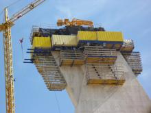
The CFT is erected on an asymmetrical hammerhead that was also built using Doka formwork technology. The 9.5m long hammerhead is considerably shorter than conventional solutions, and is constructed jointly with the first casting section (facing the River Vltava). Following this, the first CFT is erected and travelled forward, and then the second CFT is erected on the hammerhead.
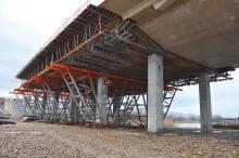
Several crucial factors enabled the erection time to be kept very short (three weeks): the completely pre-assembled 25tonne girder grille for the base formwork can be lifted into place and then exactly positioned by the CFT's powerful hydraulic cylinders; the high degree of pre-assembly of the traveller construction, and the ready-assembled large area formwork elements.
Application 'first'
Meanwhile, SGB's lightweight GASS aluminium shoring system has been used in construction of a large reinforced concrete bridge arch for the first time in this type of application.
The 140kN system includes integral brace frames and is being used by
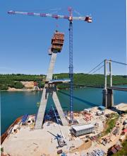
As part of the £25 million (US$40.7 million) bypass around the former mining town, the 120m long, four-span bridge features a graceful central arch reaching 24m above the river bed below. To construct this structure, Hochtief Griffiths needed a considerable amount of falsework to support the concrete forms.
Specialist contractor SGB Formwork proposed GASS, and SGB's project engineer Bob Ambrose explains: "Normally you would expect to use a system scaffold like CUPLOK to build the falsework for a bridge of this type. Although those are both cheaper options, GASS is so
much faster that the time savings in this
instance more than compensated for the extra cost of the system."
Working closely with Hochtief Griffiths, SGB developed a falsework design comprising a series of GASS towers linked to create a birdcage structure reaching from the valley floor to the crown of the bridge arch. To form the arch soffit, SGB used its MKII soldiers as supports for the timber shuttering.
The concrete was poured in stages, with side and top shutters required, to ensure that the required angle of construction demanded by the bridge design was achieved. The pouring sequence was designed so that sections were formed alternately on either side of the arch to maintain equilibrium within the formwork structure.
The vertical loads were transferred directly to the legs of the GASS towers and taken down to the ground. However, the horizontal loads were more difficult to dissipate. The birdcage structure was built in three levels with the MKII soldiers supported on top of the first and second levels. Those on the second tier of GASS towers supported the bridge arch on either side of the crown, and roughly midway between the abutments and the centre. The horizontal forces were transferred to SGB's MKII Soldiers, located along the top of the GASS towers from one side of the arch to the other, and therefore cancelled each other out.
Nearer the abutments, the MKII soldiers supporting the formwork were supported by the lower tier of GASS towers, and were also positioned further apart than those nearer the centre of the arch. SGB took the horizontal forces back under tension into the arch itself with MKII Soldiers tied into the initial concrete pours.
Tying the beams to the arch helped stabilise the formwork structure and prevent the weight of each subsequent pour pulling the arch out of shape. The alternating sequence of pours also minimised any unequal forces. SGB supplied the key components for the shuttering and associated equipment as well as designing the structure and the methodology.
PERI: one-source formwork
The D1 motorway across Slovakia, between the Austrian state border in the west and Ukraine in the east, has a planned length of 500km. Six sections (almost 300km) have been opened, and closing the 10km long gap between Sverepec and Vrtižer, near the northern Slovak city of Považská Bystrica, is under construction. Opening is planned for the end of 2010.
To construct the 767m long motorway bridge near the Centrum D1 motorway junction,
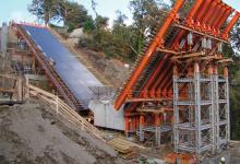
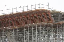
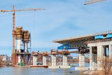
Planning and execution are based, as far as possible, on rentable PERI modular construction systems: the UP scaffolding system and VARIOKIT engineering construction kit. Construction of the hollow box cross sections for the superstructure uses UP falsework and the external web formwork with the cantilever formwork area is created with variable latticed frameworks using VARIOKIT system components (so-called raised formwork units).
"The demands placed on the construction crew and the selected formwork solutions are high in this case because the bridge cross sections as well as its longitudinal and lateral inclinations continuously change. At the same time, there is a junction point where two separate superstructures merge to form one distinct bridge structure. In the process, single and twin-spaced hollow box cross sections with variable superstructure widths are to be constructed, and this requires a high degree of flexibility and variability," says PERI.
The PERI UP supporting scaffold transfers the loads arising during construction of the superstructure (at heights of 13-15m) into the ground and through its modular structure and metric grid arrangement, the load-bearing system can be optimally adapted to deal with all forces.
PERI UP has been type-tested up to a height of almost 22m and can be used, in addition to the use as space stand, also as column framework unit and as shoring tower.
The available type test saves on time-consuming static calculations for standard applications and can be referred to for individual project static calculations as a basis for the design. Furthermore, project-specific construction drawings in combination with the assembly instructions are also part of the PERI range of services. These provide site personnel with all required detailed information including individual assembly steps.
At Považská Bystrica, the bridge's hollow box superstructure is being realised in two casting segments with the help of VARIOKIT raised formwork units. In the first cycle, the bottom plate complete with webs is formed and concreted while the carriageway slab and cantilevers are constructed in the second cycle. GT 24 formwork girders, SRU steel walers and SLS heavy-duty spindles have been accurately adapted to the structure's geometry.
The span width is 34m, which also represents the length of each individual concreting cycle. To ensure optimal building progress, the contractor had sufficient scaffold material available for three complete construction phases. While two cycles are always completely scaffolded, the third set of materials is gradually dismantled, transported to and re-assembled in the next section.
Racing ahead
RMD Kwikform Middle East's engineers have carried out the design process to help contractor Leighton Construction (Abu Dhabi) construct the eight in situ concrete box girder bridges and a tunnel required for the Saadiyat Island Expressway.
The project involves Leighton constructing a ten-lane, 6.5km long highway to link the United Arab Emirates' main city, with an exclusive island lying just offshore.
Conceived and driven by the Abu Dhabi Tourism Development and Investment Company, the arterial routeway, together with its interchanges, side roads and 1.6km of bridge decks, is scheduled to be complete in time for the inaugural Abu Dhabi Grand Prix in November.
Leighton decided to award
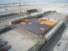
At 180m long and 80m wide, the Golf Land Bridge will not only the biggest bridge on the Saadiyat Island Expressway, but also the largest bridge (in terms of area) built to date in the UAE.
Andy Teesdale of RMD Kwikform, said: "Aside from the fact that the work will see a staggering 215,000m³ of our Rapidshor falsework either purchased or hired to the client, our involvement also involves responsibility for design detailing and site safety."
The decks to the bridges are all being designed as concrete box girders, with the 2m deep section being divided into a series of cells. The formwork has been planned and detailed so that the main elements can be pre-assembled on the ground, lifted into position and then moved again with as little adjustment as possible.
The most technically challenging requirement for RMD Kwikform to date has been the design and manufacture of special steel forms to cast the complex geometric shapes to a number of the pier heads. These were fabricated from steel to cope with the very high concrete pressures and variations in profile.
For the 870m long cut-and-cover tunnel that traverses the line of the main highway RMD Kwikform is supplying its Alform beams and Superslim soldiers to cast the walls. Then for the roof to the tunnel, the method of construction switches to the use of the specialist's table-forms. These will be assembled using the company’s Alshor Plus system, making up 30m long sections, which can be struck and advanced as a single unit as soon as the concrete has gained sufficient strength.
Mirror image in Iowa
Jensen Construction of Des Moines, Iowa, USA, is constructing the twin of a bridge it built in the state in 1970.
The company, which used
"Chuck Ulmer [carpenter foreman on the first bridge] was so instrumental in form layout on the 1970 project that Jensen brought him back as a consultant during the bidding process.
Each of the bents [part of a bridge substructure: a rigid frame commonly made of reinforced concrete or steel which supports a vertical load and is placed transverse to the length of a structure and commonly used to support beams and girders] for the project was poured in sequence: the stem wall, the 'tulip' or Y pier and the cap.
When complete, the pier and cap will have an enormous void in the centre matching the 1970 version flawlessly.
The stem walls measure 2.1m wide with variable depths , and range from 0.3m to 11.2m tall, and were formed with EFCO Plate Girder panels resting on previously poured footings. When the stem forms are cycled, support brackets are installed, two on each side of the stem, to support the massive form for the pier and cap.

