The overpass will streamline traffic by linking the Umhlanga industrial zone with the Cornubia new development area Tongat. Cornubia is a multibillion rand integrated settlement near Umhlanga, north of Durban, in KwaZulu Natal, South Africa. It incorporates industrial, commercial, residential and open spaces.
Material supplied by
Pilosio studied and provided to CMC a custom-made system from a previous project in which the two companies had collaborated. The idea was to use a tried and tested system and exploit their assets. Competitors had offered other solutions that required non-reusable wooden ribs.
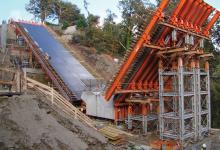
The Cornubia Boulevard Overpass is a 1.3km three-span, three-box, cast-in-situ concrete deck. Construction had to take place without interrupting the traffic flow of the highway. This led to the construction of large portholes above the highway to allow for the pre-assembling of formworks panels, installing of the rebars and deck casting operations in a complete safety process.
Another complexity for construction was that the viaduct has a longitudinal slope of 2.4°, a transversal slope of the cross section plus a pre-camber casting deck.
MP Heavy-duty support system was provided for porthole support in order to overpass the highway: HD Walls of 19.2m long and 12.27m high spanning a clearance of 16m and with a total load capacity of 1,451kN.
The deck and the wings of the bridge were poured on a plywood surface installed on a grid of secondary timber beams and main steel walings (double UPN100 profiles) formwork. The deck of the bridge was installed over supporting truss beams 150cm high and made of HE340A and double L-shaped beams, coupled by vertical braces. Adjustable foot plates, placed between the steel walings of the bridge deck and the trusses, allowed pre-camber to the casting.
The steel trusses were supported by steel beams placed over MP Heavy Duty towers. In the horizontal plane, the trusses were stiffened with tube and fittings, both on the upper and lower cords of the trusses. The stresses in the steel elements of main beams and the nodal reactions were obtained from a 3D FEM dedicated model of the structure, carried out with SAP2000 software. All static checks were done by Pilosio engineers according to EN 1993 Standard.
The foot plate extraction had to guarantee the transversal sloping of the cross section plus the pre-camber that allows the casting to have a horizontal bottom deck after dismantling the falsework. The pre-camber was obtained from a 3D FEM model of the supporting structure.
Sloping viaduct
The gross longitudinal sloping of the bridge of 2.4° was obtained with the inclination of the main trusses. The steel trusses were fixed on the left support of the portal (bolt connection) and were free to move horizontally on the right support. In this way, the horizontal actions due to sloping were applied, all on the left support - MP Heavy Duty support tower.
The MP Heavy Duty tower base jacks were fixed to the ground and braced to the lateral MP standard platform. This mitigated a tipping risk. As an alternative, cables or a ballast could be used.
As a temporary support platform, an MP Pilosio multidirectional shoring system fitted perfectly with all the site requirements. The support platforms were obtained by connecting square or rectangular modules together. Height variation between 6.5-12.7m was easily covered, thanks to the flexibility of the MP system. Two casting phases were performed. The first phase was the pouring of the bottom deck and the second phase was the pouring of the lateral vertical walls and upper slab with lateral wings.
For the deck casting, the builder chose Maximix, a formwork system made of wooden beams, steel beams and plywood panels that covers large surfaces and complex shapes with high capacity and limited weight. The capacity can be adapted to the requirements by varying the distance of the beams. Pilosio engineers created the design for the wooden deck.
Finally, Pilosio gave on-site assistance with training for assembling Maximix panels and provided shop drawings for each module. Typical designs often require an interpretation for the workers on-site. There was daily assistance for any problems during the assembly and installation of the MP towers to remedy any discrepancies detected on-site with respect to the measurements made previously.