One of the world's longest bridges is being built in Norway – for traffic volumes of just 2,000 cars/day reports Adrian Greeman
The stunning landscape of the long sea fjords in Norway is one of its glories, attracting thousands of tourists every summer. But the high mountains and deep sea inlets are also one of the great obstacles to transport and development.On the western side of the country, inland from Norway's second city of Bergen, the isolation has been causing population and economic decline. Now a century old dream of a bridge connection across the 140km long Hardanger fjord is being realised.
It is hoped that it will create jobs and educational opportunities in the region. At the same time it will provide a shorter route from Bergen to Oslo than the E16 main road running on a looping northern route which avoids the high mountains. It will also improve links to Stavanger in the south-west. Although it will have a very low traffic count the long term benefits mean it is deemed worthwhile by the Hardanger regional authority.
"Fortunately they have resources to spend from extensive hydroelectricity generated in this area," explained Øivind L Søvik, the schemes project manager for the client, the Norwegian Public Roads Administration.
Hardanger will put in 23% of the NOK 2.3 billion (US$410 million) total cost while tolls will cover 62%. Additional money will come from the savings which result when a subsidised ferry service is closed and there is around 15% of central government funding.
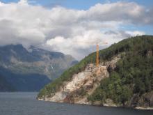
The bridge project itself needs complex design. The Hardanger is one of the great fjords, the second deepest in the country at 400m and surrounded by mountains rising steeply on either side up to 1,200m high. Spectacular though this is for the midsummer boat cruises, it makes building a crossing an engineering challenge.
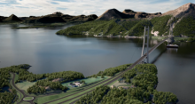
The bridge, begun in 2009 will have one of the longest spans in the world at 1,310m, ranking it ninth. With a slender deck for just two lanes it will have a long elegant form.
But extraordinarily it will have almost no back spans at all. Instead the approach roads will be through tunnels in the mountains, connected across short viaduct links of just 25m on the north side and 45m on the south.
The unusual geometry is necessary because there is no way to put the bridge pylons further out. The steep mountain slopes continue below water in the flooded glacial U-shaped valley, leaving a tight space at the shoreside. To fit the bridge into the space, the anchorages for the cables are inside the mountains rather than using more usual giant concrete blocks, as on most suspension bridges. Huge mountain masses themselves become the anchorages.
"That has been done before in Norway," said Søvik, "…though perhaps not on both sides." The design also allows the bridge to be less obtrusive in the landscape. The road authority and two major consultants have worked on the design: Norconsult for the bridge and SWECO for the roads and tunnels.
Construction began in early 2009 with the underground works, with two contracts totalling NOK400 million, both let to AF Gruppen, a Norwegian firm. The greater part of this was for two hard rock tunnels through the predominantly gneiss rock; on the north side a 700m long branch to an existing road tunnel, the 7km Vallavik built in 1985, and on the south side a new 1,100m long tunnel southwards that will replace a number of local roads. This too has a branch connecting it to the west.
"For both junctions we have made internal roundabouts," said Søvik, "…which are 55m in diameter. For each junction a rock pillar 7m across was left in the centre to reduce excavation and provide support. He said that with bright lighting these roundabouts are a good option for road safety since they will not be affected by dark days and icy weather.
A crucial part of the excavation has been for a series of chambers either side of the fjord, for which small adits were made from the main tunnel to get access. These are for the cable anchorages, where the main cables will fan out to be tied down to the rock of the mountain.
On each side there are twin splay chambers where the main cables enter the mountain and then split into 19 main strands. The wires making up each of these strand bundles are wound around a series of anchor shoes at the base of the 20m deep chambers. Those shoes are each held by two giant steel anchor bars on a plate embedded in concrete. These base plates are, in their turn, tied back through the mountain rock with huge prestress cables, two for each anchor plate.
The tie-down cables pass through a 27.1m thickness of rock to a lower chamber where they are stressed and the ends anchored into a huge concrete back "plate" held against the rock. The space for this cable tensioning work and concreting is a huge 15m high cavity that is 40m long.
Most of these chambers were excavated by drill and blast like the road tunnels and mostly went well. On the south side the splay chambers were excavated from the surface because a shallower slope made this possible and it was an easier way to make the chambers.
In general the rock for these spaces was good but on the north side there was a 3m thick band of weathered rock encountered in the splay chambers. "It meant a redesign for the splay saddles fixing," said Gunnar Ringheim, the Norwegian Road Administration’s concrete construction manager.
Setting out and fixing the cable anchor fittings in these spaces fell into the concreting works contract which was let to Norwegian contractor
Veidekke's job involved precision installation of the cable shoes and the tensioned anchoring strands locking them down. In the upper chamber this meant installing an array of 19 shoes, each held on two steel anchor bars ending in a steel plate.
The plates were embedded in a huge concave "plug" of concrete at the base of the splay chamber which had to be poured around them in one go.
"This was a precision job as the tolerance for the direction of the bars holding the cable shoes was just 2mm on a bar 160mm thick," said Ringheim. The contractor built a hefty steel frame to hold the bars in position "and we had a team of surveyors working constantly to check and recheck the positions," said Veidekke site manager Kenneth Liland. Everything had to be correct before the 2m thick concrete could be poured.
Before all that however came a drilling operation. Each plate is held by tension strand through a 27m thickness of rock, two bundles of 38 strands for each. The stressing was done through pre-drilled holes which themselves had to be no more than a few 10 millimetres off line at the far end where they emerged into the anchor chamber beneath.
Down below a huge reinforced concrete plate embeds the anchor points for the strands and this had its own complications.
But this average 1.5m thickness of concrete had to be installed with a backwards leaning angle of 51°, which meant its formwork had to be supported by a massive falsework structure until the concrete cured and the anchorage plate cables stressed through.
"It was 36m long and 18m high," said Liland's contract engineer Tom Mikalsen," and it had to hold 1500m3 of concrete with 50tonnes of reinforcement steel inside." Using a frame made from 120tonnes of steel, the concreting could be done in two halves he said, with a single
"You could not go too fast because the full mass of liquid concrete would have put too much pressure on the form; it was necessary to let it stiffen in layers slowly" said the contractor.
CONSTRUCTION SCHEDULE
•The Hardanger bridge project was approved (by the parliament) in February 2006, and shall be completed in the spring of 2013
•Design and planning period 2 years (March 2006 - May 2008)
Construction of tunnels and approach roads, construction period February 2009 - December 2010, completion spring 2013
•Construction of bridge, about 3.5 years, commenced August 2009, completion spring 2013
•Pylons and anchorages, 1.5 years
•Cables and hangers, about 1 year
•Installation of steel box girder and completion work, about 1 year
•Steel box girder and elements for cables to be produced in workshops in parallel with towers and anchorages, production time about 2 yearsA self-compacting concrete, to a Norwegian Roads Administration mix design, avoided the challenge of having to vibrate this huge mass which would have made the need for worker access even more difficult than it was already. Concrete was made in two batching plants installed on each side of the fjord for the project.
"The main quality is that it will have very little microfracturing," he said. Water penetration in small cracks and the severe freeze thaw cycles of the northern climate could reduce durability especially in the exposed concrete of the towers.
For similar, maintenance reduction reasons, the cables and their anchor chambers will be de-humidified over the lifespan of the project.
While the underground work was underway the contractor was also building the pylons, which are twin box section vertical elements linked at around 49m and 100m by deep cross beams.
First came the foundations, which on such sound rock could be simple pads, albeit on a large scale 10m by 12m and 6m deep. "That was almost 1000m3 of concrete which had to be poured in one go – it was a 60 hour operation," said Ringheim. It was necessary to use seawater piped through coils in this mass to cool it during the curing period.
The box sections with 600mm thick concrete walls were made by jump forming, rather than continuous slipforming, for two reasons. Firstly, the boxes gradually taper for both structural and aesthetic reasons and the formwork has to be constantly adjusted to reduce the box size. It begins at 7m by 8m and reduces to a square 4.5m at the top of the towers.
The contractor used a jump formwork from
But secondly, Norway's road administration has ruled out the use of slipforming as too uncertain in quality control of the curing and concrete strength says Gundersen. Jump forms moving in 4m lifts were safer and better.
The towers were completed in spring this year all the way to the top which includes a 15m wedge-like extension above the cable saddles. This is part of an overall aesthetic by Forum, an architectural firm from Bergen, aiming to make the bridge more elegantly slim looking in its stunning surroundings. The saddles themselves, made in the UK by
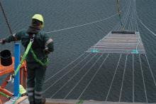
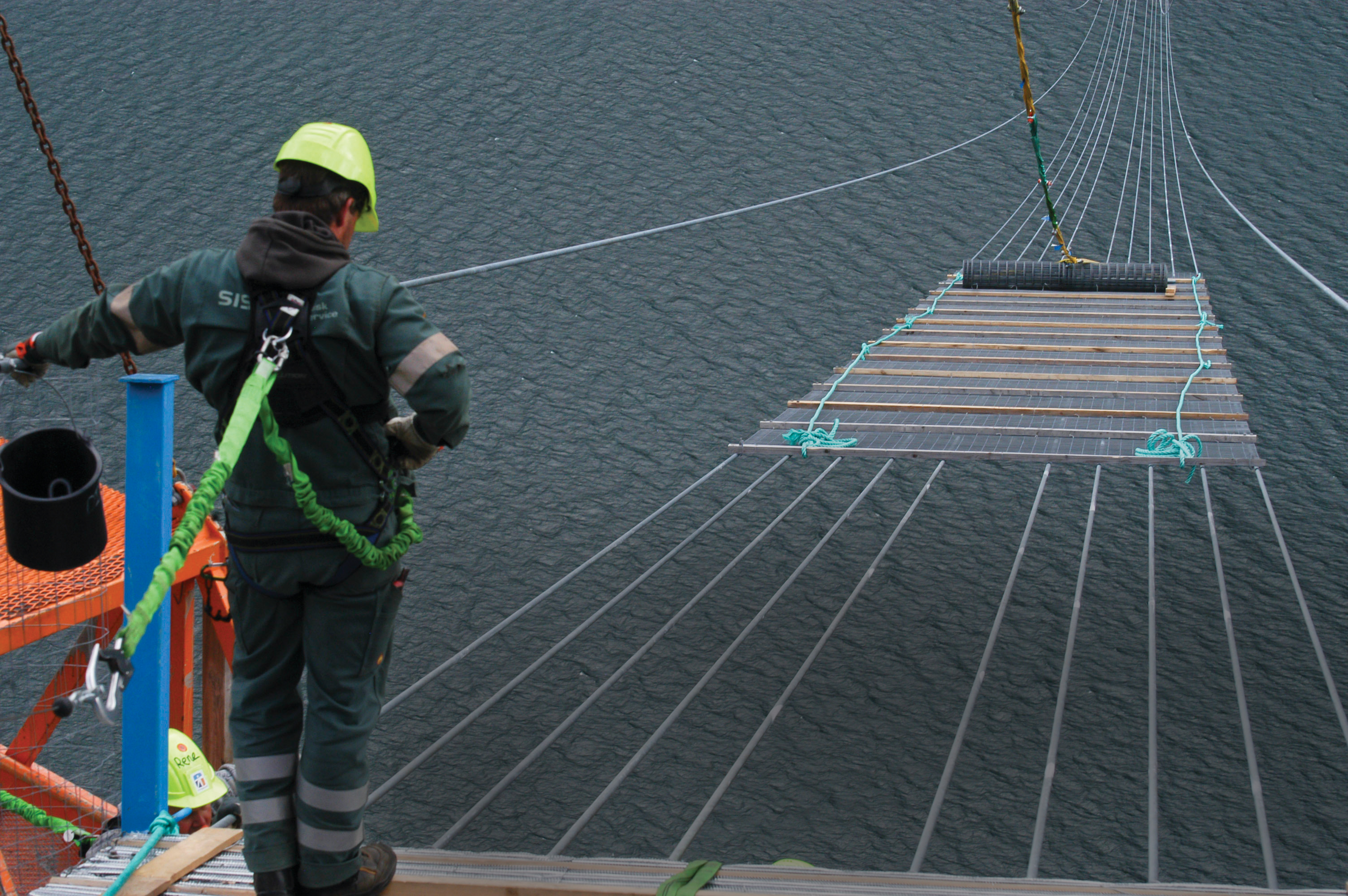
Over the late summer a catwalk has been erected either side in preparation for the cable spinning operations, due to start at the end of September but delayed until early November. Danish contractor
The UK has also supplied more than 6300tonnes of galvanised wire for the cables from specialist company
Once Højgaard has completed all this it will be time to lift in and fit the steel box sections for the road deck. These are being made in China under the supervision of a number of Norwegian inspectors at the giant
The cross section profile of the sections has undergone extensive wind tunnel testing, and now includes a number of rib projections to aid vortex shedding in the potentially high winds that can blow along the fjord. That work comes next summer when the 23 sections, each 60m long, arrive from Shanghai aboard a ship. Conveniently it can sail right up the fjord to the bridge location where the 400tonne sections will be lifted into position 55m above the water.
There they must be welded together, an operation demanding complex jacking to straighten them and adjust the angles as the load goes on to the cables and they sag more.
Finishing operations follow, with the bridge due to open in 2013.

