Iconic California crossing will offer seismic safety – Adrian Greeman reports A unique single-span single-tower suspension bridge is the iconic centrepiece of a dramatic renewal of the eastern Bay Bridge in California, crossing from San Francisco to Oakland. Tourists in San Francisco sometimes mix up their bridges, identifying as the famous Golden Gate, the double suspension bridge which runs across the wide San Francisco Bay. These serially linked bridges in fact form the Bay Bridge east to Oakland whereas

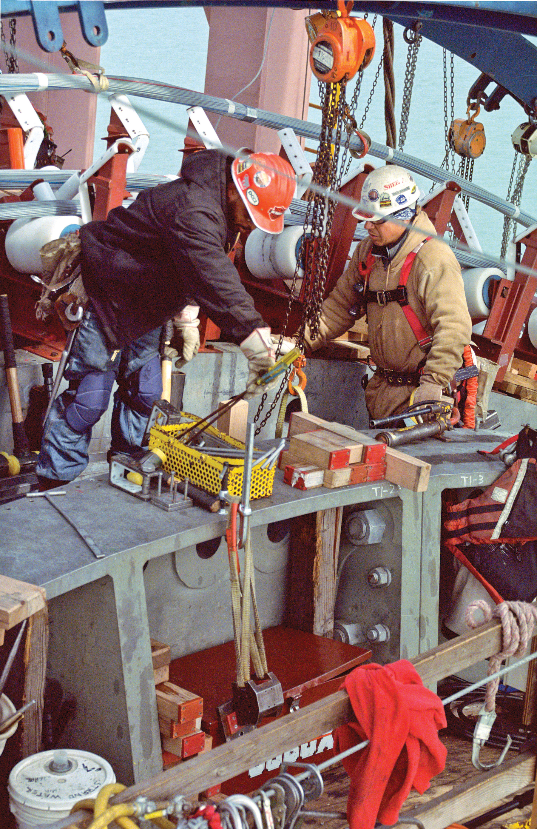
The loop haul cable was pulled up and over the tower
Iconic California crossing will offer seismic safety – Adrian Greeman reports
A unique single-span single-tower suspension bridge is the iconic centrepiece of a dramatic renewal of the eastern Bay Bridge in California, crossing from San Francisco to Oakland.Tourists in San Francisco sometimes mix up their bridges, identifying as the famous Golden Gate, the double suspension bridge which runs across the wide San Francisco Bay. These serially linked bridges in fact form the Bay Bridge east to Oakland whereas the Golden Gate spans the fast currents in the narrow entrance to the Bay, north of the city's peninsula location.
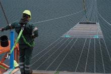
In the autumn next year another bridge will open to confuse visitors further, also deliberately an iconic structure. But this suspension bridge will be different. Firstly it sits further out into the bay, less visible from the city itself. Secondly it is a single-span single-column bridge, with cables tapering inwards from deck level to one tall pylon, forming a dramatic cat’s cradle effect of angled suspenders.
The complex bridge is also unusual in being a "self-supporting" suspension structure, which means that it does not have the usual giant anchor blocks at either end to connect in the cables and resist the loads; instead the cables will tie into the deck itself.
KEY FACTS
The main span is a 385m long self-anchored suspension bridge
The tower for the suspension bridge sits on 2.5m diameter piles keyed into rock
The curving concrete Skyway viaduct is a double box beam structure
Huge foundations with quadruple 100m long piles/pier protect the Skyway from seismic damage
The world’s largest pile-driver was required to place piles for the Skyway foundations
The innovative bridge, now reaching structural completion, is the complex centrepiece of the new eastern half of the Bay Bridge, a nearly 3km long continuation of the Bay Bridge crossing, running on from a small island in the middle of the bay where the two suspension bridges of the western half make landfall. The road passes through this Yerba Buena Island, in a short tunnel.
The relatively short but wide 565m long bridge, with a 385m main span, will cross the main east side shipping channel close to Yerba and its adjoining Treasure Island naval base, carrying five lanes of traffic each way. The road will then continue on a long curving concrete viaduct, the Skyway, for the next 2.1km, a massive double box beam structure which has been a complex and vast scale piece of engineering in itself. A final touch down section takes the traffic on to Oakland.
The now US$6.3 billion replacement is a long term solution to seismic activity, in a geographical area famous for earthquake risk. The Hayward fault is very close, within a couple of kilometres and the San Andreas within 30km. The probability of a severe shaking in the next century is very high.
Vulnerability of both west and east sides of the bridge, which both carry traffic on two levels, one for each direction, was shown in the 1989 Lomo Prieta earthquake. A fatality was caused by a span collapsing on the east side, which closed the whole crossing until repaired.
This east side is currently a giant steel truss bridge with multiple through truss spans along much of its length and a cantilever truss section for a final long span. Near the Oakland shore it has simple truss spans. It carries the road on two decks, one each way.
The suspension bridges and other elements on the west side, also double decked, have since been substantially retrofitted, with much of the deck steel replaced while traffic continued to run.
For the east side, massive strengthening was required, probably with new concrete piers and foundations. The 6.9 Richter earthquake had shown the structure had high vulnerability to liquefaction effects from the soft mud seabed in which it is founded.
But analysis by the state transport authority
"The governor also said it should be a so-called 'life line structure'," said Marwan Nader, from design engineer
The consultant is partnered by design firm Moffatt & Nichol on the crossing.
"That means the bridge must not only remain standing after an earthquake of up to 8.5 Richter, but must be usable by emergency traffic and quickly repairable to restore normal traffic use."
Initially a new concrete viaduct was to be built, and the Skyway portion of the crossing follows this principle. It would need a significantly longer span over the navigation channel but was relatively plain in aesthetic terms.
That did not suit the California public which wanted something more iconic said Nader. Via the local Metropolitan Transport Commission in 1997 it was decided to investigate a more complex element for the shipping channel.
"A panel of some 30 engineers, architects and seismic experts then solicited and examined a wide range of design ideas," said Nader. "Just about everything you can think of was considered, from single and double plane cable-stays, multispan and single span, single towers and double, symmetric and asymmetric."
Final choice was between a single concrete towered single-plane cable-stay and the self-supporting suspension bridge single steel tower, and suspension cables which tapered in from the outside of the decks to the centre, creating a waisted effect. Inclined hangers from the deck edges angled inwards to meet the changing line of the main cables.
"There were two main criteria really," said Nader. First was seismic resistance. For this, the cable stay would normally have the advantage because a suspension bridge depends on the inertia of its giant mass anchor blocks to which the cables and the loads on them are tied down.
"In an earthquake there can be a lot of energy pumped into a structure through the anchor blocks," said Nader. With no anchors the cable stay wins out.
Creating normal anchor blocks would also have been problematic in the very deep soft muds and sediments of the bay seabed Nader continued.
But if a suspension bridge can be built without anchor blocks, these difficulties are eliminated. There is such a type of suspension bridge he said, quite often used until around the period of the Second World War when cable stay design developed. "That is the 'self-anchored' suspension bridge."
For this the main cables are anchored into the deck itself at the ends. They 'pull' inwards as they are loaded, and this is resisted by compression of the main deck.
By using an "SAS" the suspension bridge could be made to work. "After seismic resistance the decision then came down to aesthetics" believes Nader. An additional factor was a lower tower on a suspension bridge which helped stay within tight limits for airport radar clearance.
The suspension bridge was a fairly expensive option likely to cost a bit under £1 billion, not least because the structure is far from "self-supporting" during construction. Unlike a normal suspension bridge the deck cannot simply be hung on the cables but must be pre-assembled so that the main cable can be connected. A large platform is needed to hold the deck temporarily.
"But cost was a lesser factor," said Nader. "This was still the dot.com period and the Bay area was doing well." At that time it would have been around $1.5 billion.
Later cost did have more of an impact especially when in 2002 the initial bids for the complex construction, to finish in 2007, came in at around $1.4 billion. Total project cost was about $2.6 billion. But by then economic conditions had altered and the project underwent a series of holdups and re-thinks, including cancellation of the initial bid process in 2004 when the state governor, Arnold Schwarzenegger declared the budget incapable of sustaining the scheme.
Extension of the plain Skyway section was to be made but eventually the state and the northern Californian areas agreed to compromise and go ahead with the suspension span in 2005. New approvals and design changes would have meant the viaduct would not be substantially cheaper than the signature span.
New bids in 2006 suggested a $1.8 billion main bridge cost though by waiving federal "buy American" requirements, this was cut back to $1.4 billion. Cables from China and steel sections from Japan are being used, the project going to a joint venture of
Adding to construction complexity and cost are extra and sophisticated features. Firstly the 161.5m tower comprises four slender steel sections; these taper inwards slightly and are linked together with "fused" cross pieces, mostly at the top. The cross members make the tower into a single lattice structure but are also breakable above certain shear loads. In an earthquake the four elements will separate, and move separately to ride out seismic shock.
The tower sits on thirteen 2.5m diameter bored piles keyed into the bedrock which is near surface at the island location. They are 60m long.
Lifting in huge tower box sections made in high grade welded steel by Japan Steel Works, and fixing them with thousands of bolts was one of the first precision tasks for the contractor. Each of the four sides was fabricated in five pieces, strand jacked into position to very high positioning tolerances.
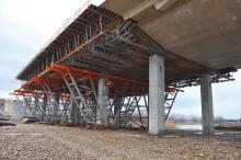
At the same time a 20,000tonnes of steel falsework had to be made across the water to support the deck section assembly, also from steel box sections brought from Japan.
Steel cable saddles with carefully designed separation channels for the cables to be seated firmly and precisely were then lifted into position. Because of specific design features there are more of these than usual, seven in all. Two main saddles sit on the tower top but others guide the splaying of the cable at the anchor points and also pass it around the back of the bridge on the short span.
This last requirement comes from a very unusual feature on the bridge, the use of a single main cable. Most suspension bridges anchor the cable ends using a splay arrangement to fan the individual cable strands out to bolting points, on the anchor block or anchor plates on the deck end for self-supporting bridges.
But tight constraints on the bridge position had given it a short back span and cables arrive to the deck at a steeper angle than the flat curve of the main span end.
"This would mean using a very deep anchor plate below the deck," said Nader. A flash of inspiration was to do away with the anchor point. Instead the cable would wrap round the back end, transferring loads through further saddle points where they changed direction.
But this produced a complex erection challenge for ABFJV when it came to cable installation. Instead of the normal straight end to end stringing of one cable either side a long cable was used. It had to be anchored and then be taken up and inwards over the tower on one side. At the end it passed down and around the back of the bridge, and then up the other side, again moving inwards on plan, to a second saddle on the central tower.
Finally, the cable passed down to the main span again before splaying out to the anchor plate bolting points.
This procedure was "simplified" by using pre-formed cable strand rather than "spinning" the cable individually wire by wire to build up the hundreds-strong cable bundle as traditionally done. "
By making the strand in a factory, in this case Shanghai Pujiang Cable Company's works, there is less risk of misplaced wires," said Nader.
“They are a very professional outfit,” said Brian Petersen project director for the JV contractor.
Cable "hauling" even with these multiwire strands, still required innovative thinking from the contractor which began the operation at the end of last year and completed in spring.
The JV came up with a kind of ski-lift. First the strand is attached by a special haul frame to a continuous loop haul cable which pulled it up and over the tower.
Once at the west (island) end the strand was unhooked from the main haul mechanism and attached to a secondary pull line, around the end of the back span. A hydraulic manipulator arm was devised for this purpose to hook on the strand socket end.
Once around the loop, the cable strand was reattached to the main haul system and passed back up and over the tower to complete a total 1,463m long journey.
Cable placing went well and compaction of the cable was completed in the summer.
The final complexity is fitting the deck hangers and attaching them to the deck. As with all suspension bridges, the loading of the deck changes the "sag" in the cable but there are additional complications.
The unloaded cable rides too high above the pre-made deck and the free hangers therefore fall short. Ends have to be brought together with the deck by jacking to reach final configuration, requiring difficult design calculations.
Tapering on plan means the hangers must also change angle as they move outwards at the deck connection point. "Altogether there is roughly 10m sideways movement and 3-4m vertically required," said Nader.
A complex three phase operation was underway this autumn, which used special extender rods on the hanger cables to incrementally jack the hanger cables by small steps, gradually transferring the deck to the hangers. When finished the temporary steelwork will be removed and then only deck asphalting, lighting and other fitting out will be needed.
Meanwhile the Skyway viaduct has been completed. Though conventional in appearance and built by well-understood concrete precast segmental balanced cantilever methods, this has also been a complex and major engineering challenge in design and construction, said T Y Lin Skyway project director Sajid Abbas.
For seismic resistance there are gigantic foundations, each of the piers supported on four enormous 100m long giant steel tube piles, 2.5m in diameter, for which one of the world's biggest pile-drivers was required, a Mancke 1700, to reach firm formation deep down in the Bay sediments. The top 50m of the piles is filled with concrete.
They support huge 17m by 20m and 6.5m deep pile caps. Rather than use concrete these were fabricated in steel using methods from the offshore oil industry.
Joint venture contractor
Concrete piers are also specially designed with through steel reinforcement. Their structure is ductile in an earthquake, giving a failure mechanism that protects the foundations and deck.
The giant segments making up the deck are also huge, up to 9m deep for the central box and 25m wide to support a five lane road above and a small bicycle path by public request.
They weigh up to 700tonnes and needed specially large transporter units at the fabrication yard.
"There are no pier top bearings for the deck. All the connections are monolithic to prevent the deck coming off" says Abbas.
Expansion joints are done with special "tube connectors" – also gigantic – in between just four "frames" along the bridge length.
The Skyway was built between 2002 and 2007.
Other complex work has been needed for a viaduct link on the midway island. To make room for this, the existing road structure had to be diverted onto a new temporary viaduct built alongside and then connected over a holiday weekend using a bridge slide operation by specialist firm


