Genoa, on the Gulf of Genoa in the Ligurian Sea, forms the southern corner of the Milan-Turin-Genoa industrial triangle of north-west Italy and is one of the country's major economic centres. For this reason alone, construction of a new bridge has significant national importance after the tragic collapse of the old bridge during a storm in August 2018, killing 43 people.
The city, with a population of around 600,000, has major shipyards and steelworks and a financial sector dating from the Middle Ages. The Bank of Saint George, founded in 1407, is among the oldest in the world and has played an important role in the city's prosperity since the middle of the 15th century. Culturally and socially, Genoa is one Italy’s greatest treasures.
However, even before the Coronavirus pandemic ripped through the economy of Italy – one of Europe’s worst-hit nations – the country’s construction sector was struggling with too many delays to major infrastructure projects. This was costing contractors, city authorities, road owners and taxpayers millions of euros in lost production capacity and increased travel times.
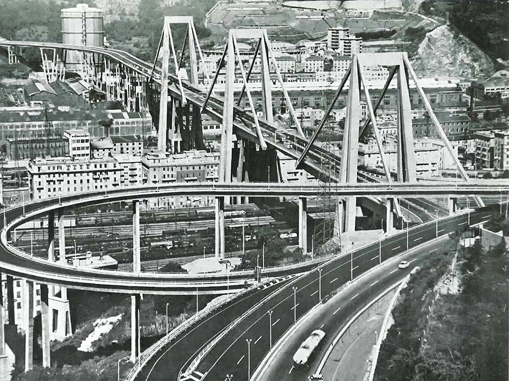
The doomed four-lane structure was often referred to as Ponte Morandi, or Morandi Bridge in English, after its structural designer the engineer Riccardo Morandi. Officially, the bridge was called the Viadotto Polcevera, or Polcevera Viaduct in English. It was completed in 1967 and traverses the Polcevera River as part of the A10 autoroute, a critical part of European route E80 that links Italy and France. The 210m main span of the 1.2km cable-stayed bridge is the one that failed on that fateful day in 2018.
Webuild, formerly Salini Impregilo, is part of the PerGenova joint venture on the US$216 million project. Webuild has made work on the bridge a badge of honour and pride for all Italy. The construction process that is delivering the bridge on time is part of what it hopes will be a new normal for construction projects in the country. It is, according to the Milan-based company, an example of what it is calling Projetto Italia, or Project Italy, in which contractors, clients and governments improve collaboration to get major infrastructure work completed with no delays.
For executive design and BIM (building information modelling) the new viaduct, PerGenova turned to Italferr, a consulting company belonging to FS - Ferrovie dello Stato, the Italian state railway company. To ensure that work on the new bridge - from design stage to opening - proceeded smoothly, a dedicated task force was established whose performance was overseen by an Extraordinary Reconstruction Commissioner.
Within this framework, Italferr was given three months to complete the executive design. To ensure it met deadlines, Italferr implemented Bentley Systems' BIM to generate and manage digital representations of physical and functional characteristics of the bridge.
BIM was used along with Bentley’s connected data environment (CDE) based on ProjectWise. The project team used Bentley Systems applications to create digital models of the terrain, road, civil works and mechanical and electrical systems. Bentley applications helped reduce design costs and improve collaboration due to faster decision-making, more accurate calculations and better management of revisions. The project is on schedule for a completion this summer.
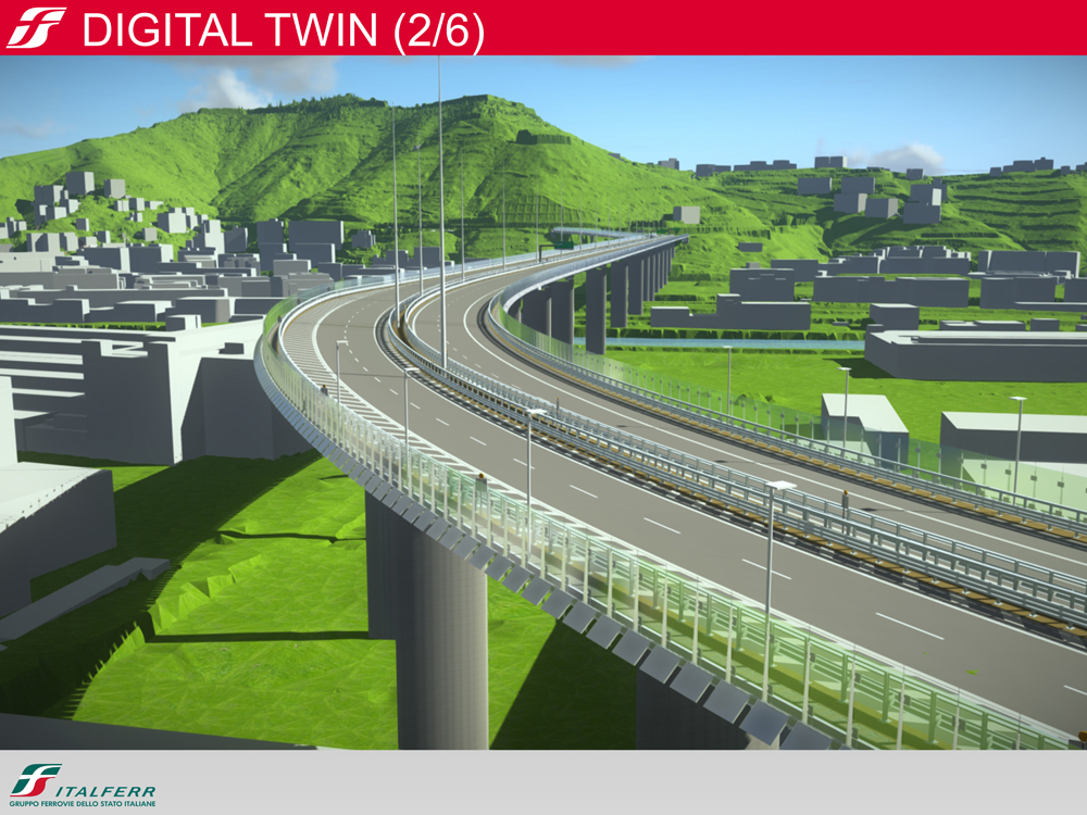
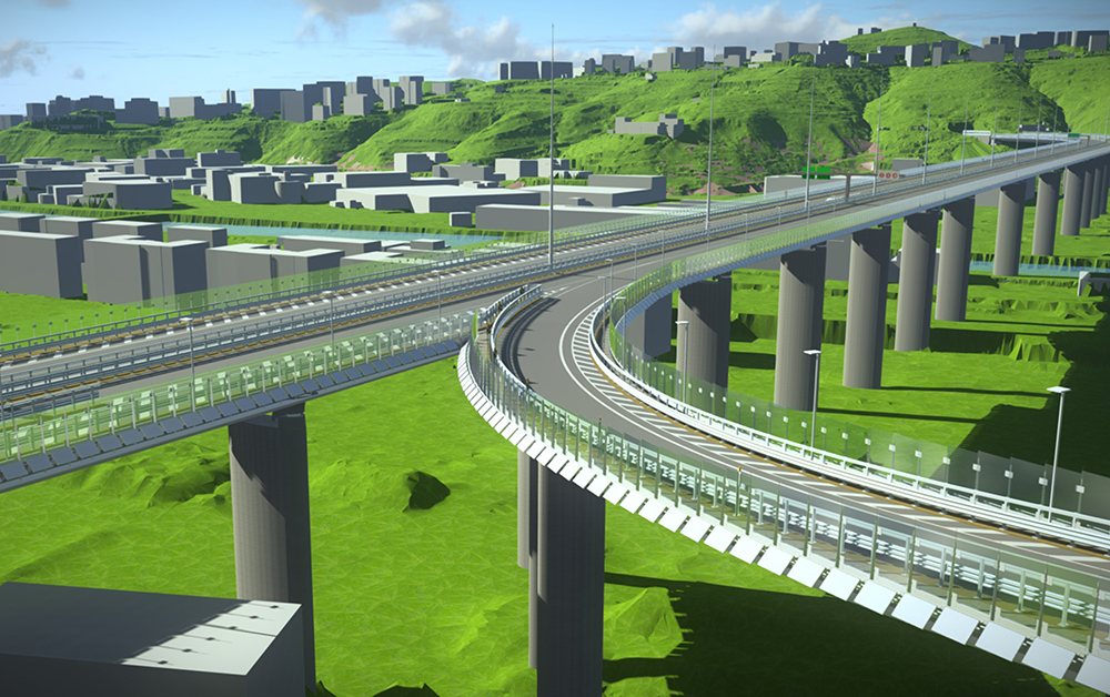
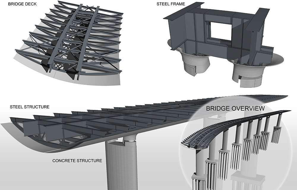
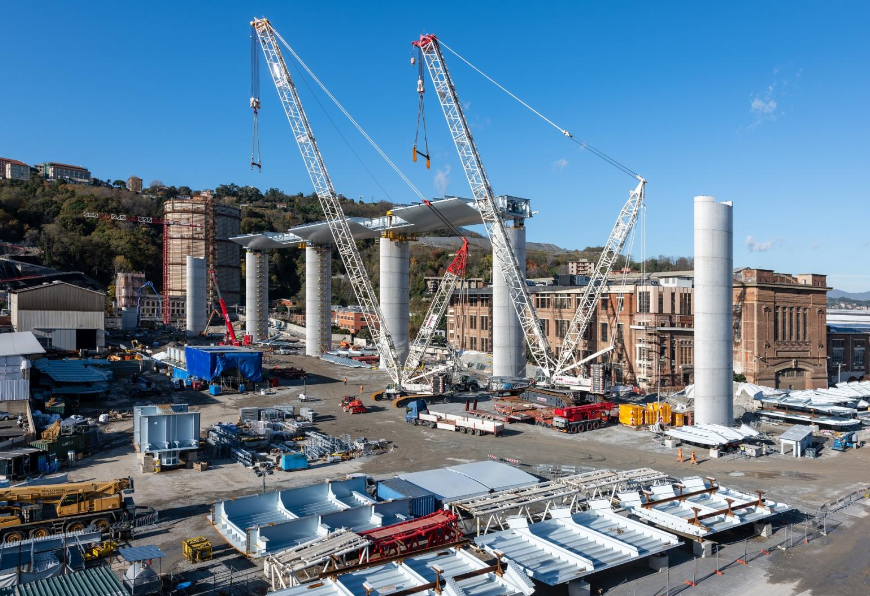
The new bridge consists of a steel main deck extending just over 1.1 km and with 19 spans: 14 of 50m length, three of 100m, one of almost 41m (approach to the west shoulder) and another of just over 26m (approach to the east shoulder).
The project has 18 elliptical (9.5m x 4m) reinforced concrete piers positioned at regular 50m intervals, except for the span over the Polcevera River and the two adjacent piers where the span distance goes from 50m to 100m. This solution enables the structures and foundations to be optimised by restricting their size in a strongly urbanised area.
Systems for maintenance and operation of the bridge are designed with good access in mind so they can be easily maintained. This also allows for continuous monitoring of their operation and their efficiency.
The viaduct is equipped with systems both on the outside at street level as well as within the deck structure and on the part of the intrados (the lower or inner curve of an arch). A services building houses power and control equipment such as energy plants, supervision systems and dehumidification systems for air inside the main deck boxes.
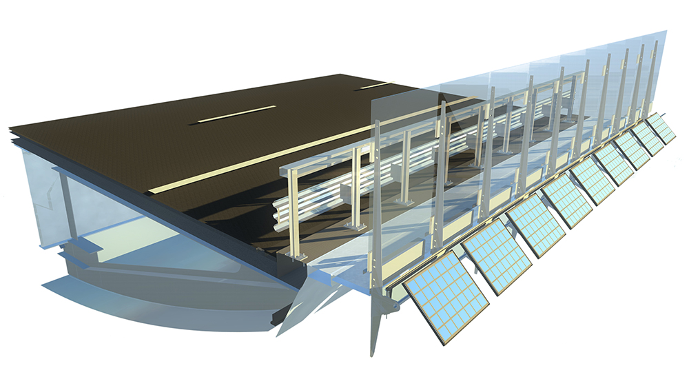
The electrical equipment is a photovoltaic system with a power of 197kWh connected to the general low-voltage switchboard of the electrical transformer cabin that powers the viaduct. Renewable energy from the photovoltaic plant runs the utilities and will be combined with a storage system of around 150kWh capacity to maximise the use of the energy for systems including street lighting, warning lights and scenographic lighting.
The solar light collection system consists of photovoltaic modules with monocrystalline silver-gray solar cells. These are installed on special structural elements along the bridge decks and ramps and inclined 45°.
The dehumidification system within the deck itself is to avoid surface condensation which would lead to corrosion of the structure - possible thermo-hygrometric conditions. The plant is composed of seven dehumidifiers with an absorption rotor placed at about 150m from each other. Each unit is positioned in the central section of the body and feeds a system of pipes that guarantees the diffusion of air throughout the unit’s immediate area. Each unit is equipped with its own control system using thermometers and humidistats.
The BIM process
Applying BIM methodology allows the exploitation of CDE (Common Data Environment) capable of managing the flow of interdisciplinary data. This guarantees traceability of data, essential for coordinating construction processes.
BIM also defined the areas and procedures to be adopted during design activities in order to create a Federated Model of the entire infrastructure, limiting the activity of modelling to some key disciplines such as layout, civil works and installations. It was also possible to integrate some design content related to other disciplines through the use of hypermodels - 2D drawings, numerical data and so on.
An information model was produced that formed the basis for subsequent phases of construction and operation and - in general - for the entire life cycle of the work.
Before proceeding with modelling of the bridge structure, an Information Management Plan (PGI) was drawn up. This established operating methods and content of the BIM informative model of the viaduct.
For each component of the model, a minimum set of data about physical elements and construction schedules was needed. This included a WBS (work breakdown structure) Identification Code to lay out the project in order to number the tasks. Other information needed was detail about material, the project’s main dimensions such as length, surface, volumes and so on, as well as an outline of the implementation phase.
To facilitate the exchange of data and information between the interested parties, a shared environment was set up using folders in which each discipline had its own work space.
The shared work environment of the BIM model allowed the assembly of numerous other models from different specialist suppliers. The man models are:
• a digital terrain triangulated model obtained through the Lidar survey;
• a digital model of the plano-altimetric (horizontal and vertical) layout of the route;
• a digital model of the new road system meaning the complete package including signs and safety devices;
• a digital model of all civil works for steel and concrete structures;
• a digital model of mechanical plants and;
• a digital model of electrical systems.
Following a preliminary survey activity through airborne flights equipped with a laser scanner, a point clouding and triangulation process was started to digitally reconstruct the context in which to operate.
The digital model of the land alone was then enriched with numerous details and information through the manipulation and insertion of shape files or three-dimensional models. To increase the detail of the information that can be obtained from the digital terrain model, orthophotos were added. An orthophoto is a geometrically corrected aerial photograph that displays ground features in their true ground position with a constant scale throughout the image. This correction process is called orthorectification.
Using the digital terrain model and triangulation of the data coming from the field surveys, a three-dimensional surface of the bedrock was developed. This allowed for precise verification of the depth of the bridge’s foundation piles.
Once a digital territorial context was defined, work started on the implementation of the plano-altimetric axis of the new viaduct in a three-dimensional context.
The tracking activity is supported by a "criteria-based design" system that ensures design choices meet regulatory standards. The result is an intelligent 3D polyline, a connected sequence of straight line segments created as a single object. It could adapt to sudden changes, complete with information about the geometric data of the path.
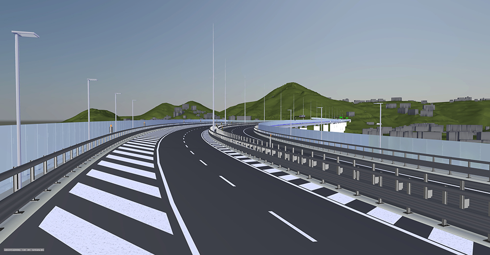
Templates were created that allowed the placing of components such as guardrails and signals. Similarly, the generation of auxiliary surfaces ensured the correct projection of horizontal signage elements along the entire route.
Considering the short deadline for design work, it was necessary to set up a structural model of concrete and metal elements that could update itself quickly and consistently with continuous design changes. The model was developed by positioning each component in a specific set of three coordinates of the modelling space. Data could be inputted that generated different solutions for concrete structures, in terms of positioning and also configuration.
Metal structures
For the design of metal structures, it was necessary that the floor diaphragms changed their geometry to compensate for any height variations imposed by the transverse rotation of the road platform. In addition to managing the transversal rotation of the metal deck - and consequently the geometric variation of all the metal components that depend upon it - shape parameters were set up that allowed variation. This was necessary to ensure coordinated welding work.
Once the geometries and dimensions of each component of the deck were defined, plant designers had a three-dimensional model upon which to accurately design and place equipment. But the design of the bridge meant that non-standard electrical and lighting systems were needed. It was, therefore, necessary to create special product families in order to integrate them with the structure and visualise their appearance, colour and technical characteristics.
Some examples are the scenographic lighting fixtures under the edge of the viaduct, the street lighting fixtures that have power supplies and diagnostics at the base of the posts and not at the edge of the lamp and the collection rods of truncated-cone atmospheric discharges installed on the uprights of the glass barriers.
An important advantage of having a BIM model was the ability to check compatibility between numerous systems of the various technological disciplines and civil works, with particular reference to restricted spaces, such as the passages at the reinforcement diaphragms of the deck.
Furthermore, it was possible to determine precisely the position of the equipment, the relative supports and the special pieces for anchoring to the structures, with particular reference to non-straight profiles. Examples include the electrified busbar inside the deck. For this, the exact radii of curvature, direction changes, expansion joints and air diffusion channels inside the box were defined.
The BIM model also supported the maintenance and disassembly, if required, of auxiliary and support systems - especially the dehumidification units. Through this verification the internal passages inside the deck caisson were also optimised and methods of supply and handling of the machines for maintenance were defined.
The BIM model also made it was possible to simulate the air flow inside the deck structure. This allowed the most efficient number of units to be installed, as well as the best place for positioning of the dehumidified air inlet nozzles.
All the aforementioned systems have been interfaced with a SCADA-type supervisory system (Supervisory Control and Data Acquisition) to guarantee their efficiency and to regulate and control their operation.
Reality imitates art
Last October, Italferr received special commendation in the award category Advancing Infrastructure Resilience through Digital Twins. The company’s scope for the new bridge includes engineering design, project management, construction site management and supervision as well as acceptance testing and commissioning.
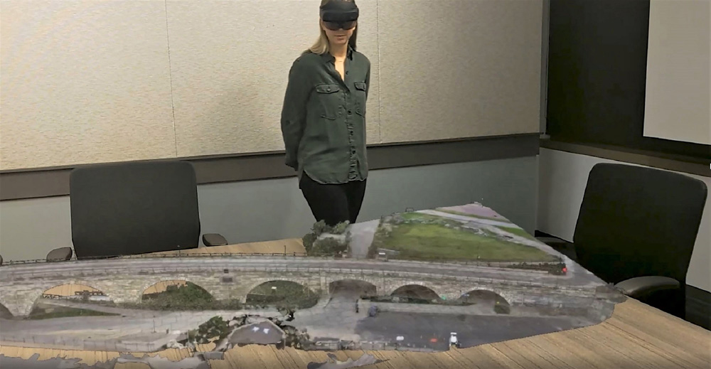
To meet the tight schedule, Italferr created a digital twin to support all BIM workflows through the executive design phase. Digital twins help the design team collaborate and simulate the performance of an asset at any point in its design.
The bridge’s digital twin was enabled through a connected data environment built upon ProjectWise that managed the flow of data coming from the multidiscipline project team using Bentley Systems' open modelling and open simulation applications. Using MicroStation, OpenRoads and OpenBuildings Designer, the project team created digital models of the terrain, road and related civil works, as well as the mechanical and electrical systems.
To simulate construction, the team used SYNCHRO to understand critical works and other complex situations. SYNCRO’s 4D digital construction environment made it possible to visualise, analyse, edit and track the evolution of the project through its implementation phases. The team linked the iModels dynamically to SYNCHRO to identify and remove potential conflicts. This made it possible to virtually simulate and optimise construction.


