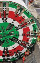
Bertha, the world’s largest diameter earth pressure balance tunnel boring machine, with a cutterhead diameter of 17.5m, is no more. Her 2.7km journey underneath the waterfront area of Seattle finished on April 4 and the power went off for the last time on an extraordinary TBM that had finally completed an extraordinary job.
“A small sidewalk job would have had more impact on city traffic than we have had,” says Brian Russell a vice president of
In fact, so little evidence of the massive project was noticeable above ground that the JV decided to literally put up a “Balloon over Bertha” to let people know she was directly underneath. The communications department had not a single call from the public saying that they had heard Bertha rumbling away.
Bertha bored beneath the core of Seattle, burrowing under 157 buildings as well as some bridges, a railroad tunnel and some large sewers, explained Russell. His experience includes a downtown Seattle twin-tunnel transit project in the mid-1980s as well as other transit projects in the city’s Puget Sound area.
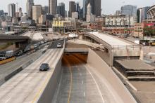
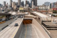
The tunnel is part of a much larger project to replace the ageing Alaskan Way Viaduct that opened in 1953. The viaduct came perilously close to sustaining terminal damage from an earthquake in 2001. The viaduct runs above the Alaskan Way street and features a double-deck elevated section of State Route 99. Sections of the 3.2km viaduct had sunk several inches. Workers stabilised the structure, but, according to the state’s Department of Transportation (WSDOT), had the quake lasted a few moments longer the viaduct would have collapsed.
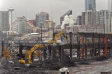
With tunnelling finished, WSDOT is combining three projects into one to save construction time, lower costs and improve efficiency. The combined project includes demolishing the viaduct, decommissioning the Battery Street Tunnel and reconnecting intersections along Aurora Avenue North. After demolition is complete, roadways, sidewalks, street lighting and other elements will be restored to a temporary condition until the City of Seattle builds the new waterfront.
Flexible
“The segmented tunnel liner addresses itself well to ground movements. Also, being underground means that, unlike structures resting on top of the ground, the tunnel has no great mass that would shift around in the event of a quake,” says Russell.
Composed of segments – nearly 15,000 were used - means the tunnel is flexible and so can absorb ground movement. “Every 2m we have a joint. I’d say the tunnel is like a big Slinky toy. The roadway inside the tunnel is actually part of a frame and the frame need not be as flexible as the tunnel. But the two together makes the overall structure extremely flexible.”
A Slinky is a pre-compressed helical spring invented in the US as a toy in the mid-1940s. It’s basic movement of travelling up and down stairs and reshaping itself demonstrates a form of linear elasticity. For the Alaskan Way, the concept is not new. Similarly designed transit tunnels exist in Seattle but their diameters are only around 5.8m at most.
“What also makes this tunnel unusual is its large diameter and segments. Instead of a 255mm-thick segment, we have a segment of nearly 610mm. It’s been a matter of scaling up, made easier thanks to improvements in tunnel alignment technology,” says Russell.
Twin-bore would have been expensive. “For years this project was simply to dig a big trench in downtown Seattle, a cut and cover project. The city and state did a lot of work to realign the highway to allow for a single-bore request-for-proposal in 2009,” he says. “Advantages of a single bore include no cross-passages. You can’t build these anyway until after the main two tunnels are finished. Then you need room to merge the single roads and tunnels. A larger tunnel eliminates these issues.”
The sheer size of the tunnel is impressive. But what is equally impressive – and little appreciated by the public, says Russell – is the logistics of a single-bore double-deck tunnel. “The trick is to work yourself out of the tunnel but not make it increasingly harder to extract yourself and equipment.”
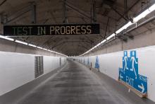
On many tunnelling projects, the road or rails are laid after completion of boring. Not so with the Alaskan Way, he says. The upper road deck was being built directly behind Bertha all the while bored material moved on conveyors over and past the formwork. Meanwhile, supply vehicles moved forward under the formwork to reach Bertha. As Bertha moved forward, so did the formwork supplied by
Burch is responsible for everything that goes on in the tunnel, apart from TBM activity. Included are the cut-and-cover work at the tunnel’s south launch pit and north end, construction of the double-deck road inside the tunnel and all onsite operational buildings.
“Everything we use is built for speed,” says Burch. “We built the rebar cages for the corbels outside the tunnel. Everything that is possible to prefabricate is prefabbed and shipped to accommodate time restraints.”
The tunnel liner can vary around 150mm in any direction but the alignment of the roadway has to be exact. “So, we survey out in front for any deviations that the tunnel liner will have versus the roadway. We adjust that 15-20 concrete pours ahead so that the rebar fabricator can adjust his rebar dimensions accordingly for each corbel section that we place. This ensures exact road alignment,” says Burch.
The corbel concrete is normal minimum design of around 27,600kPa but tested up to nearly 48,300kPa. Rebar in the corbels at road level have an epoxy coating because at this level corbels are more susceptible to water as well as vehicle exhaust corrosion than concrete higher up the roadway tunnel walls.
One of the trickiest aspects was arranging the concrete pours in a sequence, says Burch. “The issue is how to time them for optimal use of time and amount of formwork that has to be done to allow smooth pours.”
Alignment
Aligning the tunnel was critical, as well as locking the tunnel liners into place, says Chris Dixon, project director with Seattle Tunnel Partners. “Years ago, tunnel segments wouldn’t always butt-up to each other in a ring or a ring wouldn’t necessarily butt-up to its next ring. But now these line up perfectly,” says Dixon.
“A deviation of 15.24cm is normal and in this case for ascribing the tunnel we have a 30.5cm bullseye. The TBM followed the bullseye and the path could vary around 15cm in any direction which meant we were building the tunnel larger than we needed to accommodate the interior structure. This space to play with makes a tunnel’s path less critical for the correct alignment of the road,” he says.
Improvements in technology for detecting ground movements have meant more data for detailing increasingly smaller ground shifts on the surface. “Given the size of this tunnel drive, it was remarkable that we did the whole tunnel drive with virtually no surface movement. And we were at times within 4.5m of the foundations of the viaduct overhead.”
Roughly, it took an hour to do a shove and an hour to build the rings – so every two hours the tunnel advanced 2m. But TBMs operate 60-70% of the time because of maintenance and supply deliveries, explains Dixon. “We could complete around six rings a day but we had some days where we finished 13 rings when soil conditions were very good and the machine was operating 100% of the time.”
Statistically impressive and logistically challenging was the amount of grouting for the rings and soil stablising additives that had to be trucked daily from the southern portal to Bertha as she ploughed ahead. There was also the challenge of removing such a large amount of slurry once it had been carried via the ribbon conveyor to the south portal.
Bertha explained
Seattle Tunnel Partners had Bertha designed and manufactured at a cost of US$80 million by Hitachi Zosen in Osaka, Japan. She was the world's largest diameter earth pressure balance tunnel boring machine. At 99m long, she weighed 6,100tonnes. The cutterhead diameter of 17.5m held 122 disc cutters and 255 replaceable knife bit cutters. Rotational speed was up to 1.8 revolutions per minute. Hitachi Zosen shipped the TBM in 41 sections to Seattle where it arrived in April 2013 and was fully assembled by June to start its journey. The TBM was christened Bertha after Bertha Knight Landes, Seattle's only female mayor, in office 1926-28.
Soil excavated by the rotating cutter wheel passes into the excavation chamber immediately behind the cutterhead. The excavation material is removed from the plenum - excavation chamber - by an auger conveyor – cochlea – onto a ribbon conveyor that allowed a larger diameter of debris – in Bertha’s case up to nearly 1m - to funnel out of the TBM.
As the machine advances, the excavated soil enters the pressurised head chamber. The soil is extracted from the head chamber and flows along the screw conveyor to the discharge outlet where it is discharged at atmospheric pressure onto a conveyor belt. The rotational speed of the screw and the opening of the upper auger conveyor driver influence the soil flow rate and pressure gradient along the screw conveyor. Controlling the rate of soil discharge and pressure gradient along the screw conveyor regulates the head chamber pressure supporting the tunnel face.
If the machine advances steadily, a reduction in the screw conveyor extraction rate will cause an increase in pressure at the excavation chamber. Correspondingly, an increase in extraction rate will result in a reduction of chamber pressure. This method is especially efficient for boring through soft, wet or unstable ground, such as for the Alaskan Way project. Bertha moved ahead at around 2m increments and also installed the tunnel’s concrete walls before moving itself forward again. To stablise soil around itself, the TBM applied pressure by way of a mud mixture to the front of the tunnel and by a grout material between its sides and the tunnel wall.
Crews worked to isolate as much as possible the structures at ground level believed to be most at risk from soil settlement. Hollow pipes drilled into the ground at an angle around a building were filled with concrete or a similar heavy material, effectively stiffening the soil. For some buildings that were above the TBM, crews pumped material directly into the soil. This created a more continuous barrier between the TBM and the building.
The journey
It was supposed to be a 14-month bore when Bertha started her 2.7km journey in July 2013. But in December 2013, the machine stopped when the main bearing seal was compromised and the crippled machine had to be extracted from the ground.
Tunnelling resumed in December 2015 only to be again halted about a month later because a sinkhole had formed within the tunnel's work zone. Bertha was back on track the next month. In September 2016 Bertha passed the tunnel’s halfway mark of 1.4km.
Bertha finally broke into daylight in the northern extraction pit – north portal - on April 4 this year. She then fell silent and welders with cutting torches fell upon her. The largest piece that Seattle Tunnel Partners lifted out of the pit weighed just over 63tonnes. By August, the last piece of Bertha was lifted out of the pit.
But very little of the 6,100tonne behemoth was reusable, with the exception of some steel on the cutterhead that trucked to a local recycler. However, some pieces of the cutterhead were donated to Seattle and some of the cutting tools and control panel sent to Seattle’s Museum of History and Industry.
Bertha may be gone, but legal wrangles over delays continue.
Dismantling Bertha after she broke into the northern reception pit in April had two aspects. Only the front shield area was actually in the pit. The rest of Bertha lay back inside the tunnel. While the front was being cut up, the TBM’s three gantries - all on rails, and all trailing machinery still inside the tunnel - were being dismantled for trucking back down the tunnel and under the ongoing deck formwork systems to the southern launch pit for loading onto trucks.
Concurrent dismantling of the shield and trailing machinery saved time and money. “We couldn’t start work placing the prefabricated lower deck concrete panels until we had all the trailing gear out,” says Dixon.
Peri formwork
The task that Peri US faced was to develop a mobile formwork system to shutter and concrete the reinforced concrete construction within the circular tunnel tube. Execution was in three phases: the corbels, side walls and slabs. The slabs form the base for the upper road deck. There were also cast-in-place walls above the elevated slab formed with Peri’s Domino formwork solution.
A wide range of conditions were to affect design of the formwork, such as numerous tunnel curves as well as lateral inclinations of the slabs. As all tunnel-boring machine formwork carriages are designed to be moved along one rail system through the entire tunnel, specific planning of the concreting sections was particularly important for ensuring efficient implementation.
Bertha had to be constantly supplied with material for maintenance such as oils, foam agents, greases and annular mortar as well as crew changes and concrete ring segments that the TBM was installing as it moved along.
This logistics requirement for Bertha meant that formwork could not impede the roadway – this was the bottom of the tunnel which was concreted to allow passage of logistics vehicles to reach Bertha. Carriages for the formwork were eventually designed to accommodate 16.45m-long sections, based on the expected average drilling rate of Bertha. Importantly, the formwork had to move ahead to keep pace with Bertha’s drilling schedule and the TBM’s completed concrete ring installations.
Initially, the construction team levelled and concreted the tunnel floor upon which rails were installed for moving the corbel formwork carriage. In addition, a flat working surface was created for the starting unit that formed the foundation of the entire construction.
Who’s who
Lead agencies:
City of Seattle - responsible for viaduct traffic operations and minor maintenance. In
addition, the City owns and maintains Alaskan Way, the area underneath the viaduct and many of the utilities in the project area.
Main contractor:
Seattle Tunnel Partners - a joint venture of New York-based
Field service including tunnel formwork:
Peri Formwork Systems, a Peri US subsidiary, based in Woodland, Washington state
Subcontractors:
Frank Coluccio Construction and Mowat Construction for construction.
HNTB Corporation and Intecsa-Inarsa for design.
Lower deck road panel prefabrication:
Concrete Technology Corporation, based in Tacoma, Washington state, has been prefabricating the panels since the start of 2017.
The starting unit formed the foundation for the rising side walls of the inner tunnel. The unit also subsequently served as a support for the prefabricated panels that were installed as the bottom carriageway slab after the in-situ concrete work had been finally completed.
After the foundations had reached the required minimum strength, the 4.5m-high side walls of the inner tunnel were concreted directly on the starters. For this purpose, two formwork sets consisting of Maximo panels were used. This formwork was moved from concreting section to concreting section on a second carriage.
While one set of formwork remained in the rear tunnel section after the concrete had been placed, the second formwork set was reassembled further ahead in the tunnel after striking.
In the third construction phase, a slab was constructed that subsequently formed the carriageway which eventually will carry southbound traffic. The bottom slab was constructed with six slab formwork carriages using the back-step construction method: three slightly longer carriages with project-specific formwork on the basis of Variokit Steel Walers and GT 24 Formwork Girders served to carry out concreting in advance for the slab sections. The resulting interstitial spaces were subsequently using three slightly shorter slab formwork carriages.
Most of the system components were supplied from a Peri rental equipment park which reduced transportation costs and allowed quick selection of equipment as required, making the solution particularly cost-effective. In addition, the use of hydraulic solutions for shuttering and striking in certain areas facilitated faster working. The travellers also were advanced hydraulically.
Finishing off
After boring concluded in April, Seattle Tunnel Partners began transforming Bertha’s northern launch pit into a section of the SR 99 tunnel. This will include building the ‘lid’, essentially the top of the tunnel, a slab of reinforced concrete nearly 1.4m-thick. This will allow construction of buildings over the tunnel.
Next year, final connections will be finished between the tunnel’s portals and SR 99, making the tunnel ready for traffic. Throughout 2019 surface street improvements near the tunnel’s south portal will be worked on.
By 2019, the old viaduct will be completely demolished, including many of the structure’s 397 foundations and footings to around 1.5m below ground. A demolition company will be chosen in early 2018 on a design-build contract.

